Posts

DESTRUCTIVE AND NON-DESTRUCTIVE TESTING

 DESTRUCTIVE AND NON-DESTRUCTIVE TESTING Testing is the physical performance of the operations to determine the qualitative measure to certain properties such as mechanical. Testing aims to determine the quality. Types of Testing- There are two types of testing 1. Destructive Testing 2. Non-Destructive Testing 1. Destructive Testing The destructive testing is the testing in which test piece or specimen is destroyed during the test. After testing the specimen remain no longer to useful for further use. The following destructive test are- a. Tensile testing (TT) b. Bend testing (BT) c. Impact testing (IT) d. Nick-break testing (NBT) e. Hardness testing (HT) f. Etch testing (ET) 2. Non-Destructive Testing The Non-destructive testing is the testing in which test piece or specimen is not destroyed during the test. After testing the specimen is useful for further use. The following non-destructive test are- a. Visual testing (VT) b. Stethoscopic test (ST) c. X-Ray & Gama Ray test d

ADDITIVE MANUFACTURING PROCESS STEPS

Image
AM PROCESS STEPS Additive Manufacturing involves a number of steps that move from the virtual CAD (Computer Aided Design) description to the physical resultant part. Different products will involve Additive Manufacturing in different ways and to different degrees. Small, relatively simple products may only make use of Additive Manufacturing for visualization models, while larger, more complex products with greater engineering content may involve Additive Manufacturing during numerous stages and iterations throughout the development process. All the Additive manufacturing processes have the following eight common steps- Step 1- 3D model creation Step 2- STL file creation Step 3- STL file transfer Step 4- Machine set up Step 5- Build Step 6- Part removal Step 7- Post processing Step 8- Applications Step 1- 3D model creation All Additive Manufacturing parts must start from a software model that fully describes the external geometry. This can involve the use of almost any CAD solid modelin

ADDITIVE MANUFACTURING

 ADDITIVE MANUFACTURING "Additive manufacturing (AM) or additive layer manufacturing or 3D printing, a computer controlled process that creates three dimensional objects by depositing materials in the form of layers or fine droplets." It is defined as additive because the material is added sequentially, as opposed to more traditional (subtractive) manufacturing where material is removed from a solid block until the final part is left. The concept had been around since the 1940s, Hideo Kodama of the Nagoya Municipal Industrial Research Institute developed the earliest 3D printing manufacturing equipment in 1980, when he invented two additive methods for fabricating 3D models. History of Additive Manufacturing 1940s and 1950s The general concept and procedure to be used in 3D-printing was first described by Murray Leinster in his 1945 short story Things Pass By. 1970s Johannes F Gottwald patented the Liquid Metal Recorder. It was continuous Inkjet metal material device. 1980s I

TURBOFAN ENGINE

Image
TURBOFAN ENGINE The turbofan engine is a combination of the turbo prop and the turbojet engines combining the advantages of both. The turbofan or fanjet is a type of airbreathing jet engine that is widely used in aircraft propulsion. The word "turbofan" is a portmanteau of "turbine" and "fan": the turbo portion refers to a gas turbine engine which achieves mechanical energy from combustion, and the fan, a ducted fan that uses the mechanical energy from the gas turbine to accelerate air rearwards. Thus, whereas all the air taken in by a turbojet passes through the combustion chamber and turbines, in a turbofan some of that air bypasses these components.  In the 1950s, Rolls-Royce introduced the first turbofan in the world, namely, RB.80 Conway. Classification 1. According to Fan Location (a) Forward Fan Turbofan Engine (b) AFT Fan Turbofan Engine 2. According to Spools (a) Single Spool Turbofan Engine (b) Double Spool Turbofan Engine (c) Triple Spool Turb

TURBO-PROP ENGINE

Image
TURBO-PROP ENGINE (OR) TURBO-PROPELLER ENGINE A turboprop engine is a turbine engine that drives an aircraft propeller. It is very similar to turbojet engine. In this type, the turbine drives the compressor and propeller.  The world's first turboprop was designed by the Hungarian mechanical engineer Gyorgy Jendrassik. Jendrassik published a turboprop idea in 1928, and on 12 March 1929 he patented his invention. Classification of Turboprop Engine 1. According to Spool (a) Single Spool Turboprop Engine (b) Double Spool Turboprop Engine (c) Triple Spool Turboprop Engine 2. According to installation (a) Pusher type Turboprop Engine (b) Tractor or Puller type Turboprop Engine Construction It consists of: (1) Diffuser (2) Compressor (3) Combustion chamber (4) Exhaust nozzle (5) Reduction gear and (6) Propeller Working Air from the atmosphere enters into turbo prop engine. The air velocity gets reduced and its static pressure is increased by diffuser. Then the air passes through the rotar

TURBOJET ENGINE

Image
TURBOJET ENGINE The turbojet is an airbreathing jet engine, typically used in aircraft. It resembles the simplest form of gas turbine. It was separately coinvented by the two fathers of jet engines: Frank Whittle from Britain and von Ohain from Germany. The first airplane powered by a turbojet engine was the He178 German aircraft powered by the He S-3 engine on August 27, 1939. Types of Turbojet Engine 1. According to Power 1. Nuclear Turbojet Engine 2. Non-Nuclear Turbojet Engine 2. According to reused of exhaust gases 1. Afterburner Turbojet Engine 2. Non-afterburner Turbojet Engine 3. According to Spool 1. Single Spool (a) Axial flow compressor types (b) Centrifugal flow compressor types (i) Single entry types  (ii) Double entry types (c) Axial-Centrifugal flow compressor types 2. Double Spool Construction It consists of: 1. Diffuser. 2. Compressor. 3. Combustion chamber. 4. Turbine  5. Exhaust nozzle. 1. Diffuser - The function of the diffuser is to convert the kinetic energy of t

PULSE JET ENGINE (OR) FLYING BOMB

Image
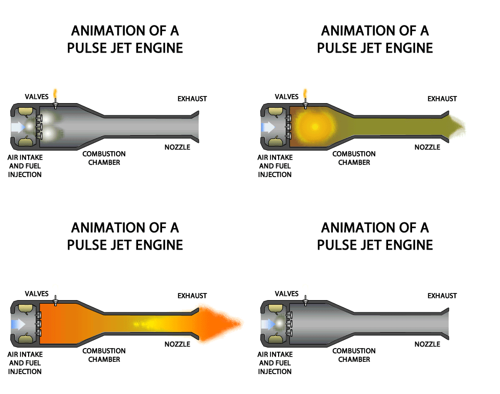
PULSE JET ENGINE (OR) FLYING BOMB A pulsejet engine (or pulse jet) is a type of jet engine in which combustion occurs in pulses. A pulsejet engine can be made with few or no moving parts, and is capable of running statically (i.e. it does not need to have air forced into its inlet, typically by forward motion). Pulsejet engines are a lightweight form of jet propulsion, but usually have a poor compression ratio, and hence give a low specific impulse. Types of Pulsejet Engine There are two types of pulsejet engine- 1. Valved Pulsejet Engine 2. Valveless Pulsejet Engine 1. Valved Pulsejet Engine Valved pulsejet engines use a mechanical valve to control the flow of expanding exhaust, forcing the hot gas to go out of the back of the engine through the tailpipe only, and allow fresh air and more fuel to enter through the intake as the inertia of the escaping exhaust creates a partial vacuum for a fraction of a second after each detonation. This draws in additional air and fuel between pulse

RAMJET ENGINE

Image
RAMJET ENGINE A ramjet is a type of athodyd (where athodyd stands for Aero THermODYnamic Duct ) airbreathing jet engine that was first proposed by Rene Lorin in 1913 . It uses the forward motion of engine to compress the incoming air, without a rotary compressor. Thus a ramjet is much like a valve less pulsejet but it operates with continuous combustion rather than the series of explosions that give a pulsejet its characteristic noise. The ramjet has been called a flying stovepipe, because it is open at both ends and has only fuel nozzles in the middle. Construction It consists of: 1. Supersonic diffuser 2. Subsonic diffuser 3. Combustion Chamber  4. Discharge nozzle  The function of supersonic and subsonic diffusers are to convert the kinetic energy of the entering air into pressure energy. This energy transformation is called ram effect and the pressure rise is called the ram pressure. The function of nozzle is to convert pressure energy of gas into kinetic energy. Working Air fr

JET PROPULSION

Image
JET PROPULSION "Jet propulsion is the propulsion of an object in one direction, produced by ejecting a jet of fluid in the opposite direction." The principle of Jet Propulsion is obtained from the application Newton's third law. i.e., For every action there is an equal  and opposite reaction. When a fluid is to be accelerated, a force is required to produce this acceleration in the fluid. At the same time, there is an equal and opposite reaction force acting on this fluid. This opposite reaction force of the fluid on the engine is known as thrust. Hence it may stated that the principle of jet propulsion is based on the reaction principle. Any fluid can be used to achieve the jet propulsion principle. Thus water, steam, and combustion gases are used to propel a body in a fluid. But there are limitations imposed upon the choice of the suitable fluid when it is applied to the propulsion bodies. CLASSIFICATION OF JET PROPULSION Jet Propulsion engines may be classified broadl

ROCKET STAGING

Image
 ROCKET STAGING All rockets use the thrust generated by a propulsion system to overcome the weight of the rocket. For full scale satellite launchers, the weight of the payload is only a small portion of the lift-off weight. Most of the weight of the rocket is the weight of the propellants. As the propellants are burned off during powered ascent, a larger proportion of the weight of the vehicle becomes the near-empty tankage and structure that was required when the vehicle was fully loaded. In order to lighten the weight of the vehicle to achieve orbital velocity, most launchers discard a portion of the vehicle in a process called staging.  Types of Staging- There are two types of rocket staging- 1. Serial Staging 2. Parallel Staging. 1. Serial Staging In serial staging (sometimes identified as tandem or vertical staging), the first stage is at the bottom and is usually the largest; the second stage and subsequent upper stages are above it, usually decreasing in size. The first-stage en