Centrifugal Pump
Centrifugal Pump
"Centrifugal pump is a hydraulic machine which converts mechanical energy into hydraulic energy (i.e. pressure energy) by the use of centrifugal force acting on the fluid. "
A centrifugal pump is the simplest machine which is used in various industries as well as in many daily applications to transfer fluid from lower head to higher head.
Centrifugal pumps are mostly used in chemical industries for easily transfer viscous fluids. Also, it is less expensive than other pumping devices. In short, it is an excellent machine with efficient working in variety of applications.


History of Centrifugal Pump-
1475- Italian engineer Francesco di Giorgio Martini designated mud lifting machine as a centrifugal pump.
1687- Denis Papin developed the first true centrifugal pump which was one with straight vanes that was used for drainage.
1851- John Appold, who was a British inventor, developed the first curved vane centrifugal pump.
Working Principle of Centrifugal Pump-
Centrifugal pumps are a category of Dynamic pumps.This pump works on basic principle of change in angular momentum. It state that the change in the angular momentum of a rotating particle is equal to the applied force. It means when a certain amount of liquid is rotated with the help of external agency means turbines or electric motor or external force, a centrifugal force acts on it which further turns into pressure. In addition to, this as liquid passes through revolving wheel then there is change in angular momentum of rotating wheel or impeller which generates more amount of pressure. In short, in a centrifugal pump kinetic energy of impeller is converted into pressure energy of fluid which is used to raise up it to certain height. Due to centrifugal force acting on water or fluid, it is lifted up to particular height. So these pump is called as centrifugal pump.

Main Parts of Centrifugal Pump-

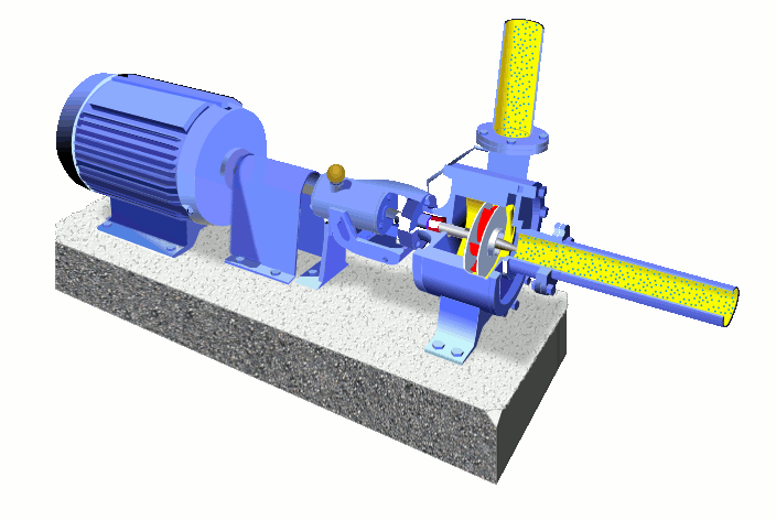

The wet end of the pump includes those parts that determine the hydraulic performance of pump. The two primary wet ends are the impeller and casing.


2.) Mechanical End Components:

1.) Wet End Components:
The wet end of the pump includes those parts that determine the hydraulic performance of pump. The two primary wet ends are the impeller and casing.
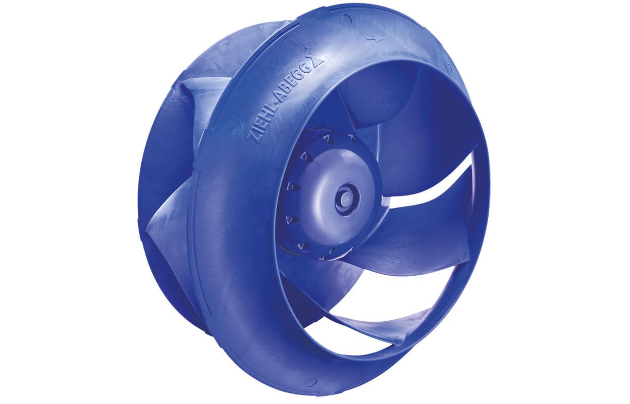
(a) Impeller-
Impeller is a rotor used to increase the kinetic energy of the flow. The Impeller are three types-
a.) Open impeller: This impeller is without crown and base plate. This type of impeller is useful in removing liquid containing solid particles such as water containing sand, paper pulp etc.
b.) Closed impeller: Closed impeller has vanes which contain cover plates on both sides. It is mostly used in obtaining pure water.
c.) Semi-open impeller: It has only base plate and don’t has any crown plate. It is comfortable with fluid containing charged debris.
The impeller blades can be:
- Backward-curved blade design (prefered design due to negative slope of performance curve)
- Radial blade design
- Forward-curved blade design (due to positive slope conditions this design can cause pump surge)
Impellers can be either:
- Single-suction. A single-suction impeller allows liquid to enter the center of the blades from only one direction.
- Double-suction. A double-suction impeller allows liquid to enter the center of the impeller blades from both sides simultaneously. This reduces forces exerted on the shaft.
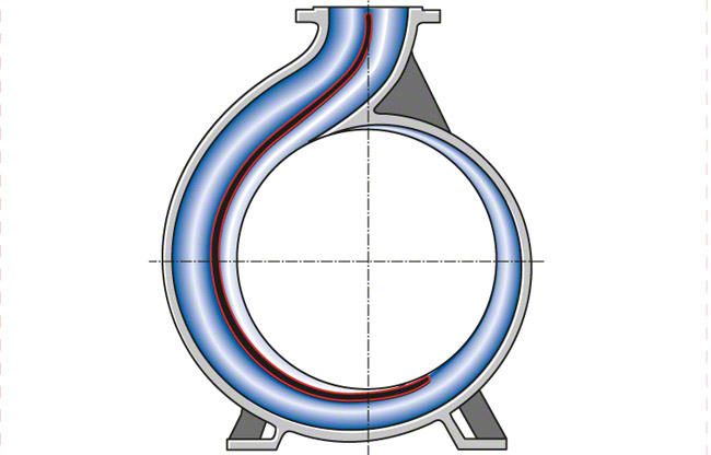
(b) Casing-
It is an air tight passage which surrounds the impeller. The design of the casing is done in such a way that it is capable of converting the kinetic energy of the water discharging from the outlet of the impeller into pressure energy before it leaves the casing and enters into the delivery pipe.
Commonly three types of casing are used in centrifugal pump and these are
(i). Volute Casing: It is a spiral type of casing in which the area of flow increases gradually. The increase in area of flow decreases the velocity and increases the pressure of the liquid that flows through the casing. The volute is a curved funnel that increases in area as it approaches the discharge port. The volute of a centrifugal pump is the casing that receives the fluid being pumped by the impeller, slowing down the fluid’s rate of flow. Therefore, according to Bernoulli’s principle, the volute converts kinetic energy into pressure by reducing speed while increasing pressure.
(ii). Vortex Casing:These have vanes which surrounds impeller periphery and convert kinetic energy into pressure energy.In vortex casing, a circular chamber is introduced in between the impeller and casing. This is done in order to prevent the loss of energy due to formation of eddies. The efficiency of the vortex casing is more than that of the volute casing.
(iii). Casing with Guide Blades:In this casing, the impeller is surrounded by series of guide blades. The guide blades are mounted on a ring which is called as diffuser. A diffuser is a set of stationary vanes that surround the impeller. The diffuser directs the flow, allows a more gradual expansion and therefore increases the efficiency of the centrifugal pump.The design of the guide vanes are kept as such that the water which is leaving the impeller enters the guides without shock. The area of the guide vanes increases; this helps to decrease the velocity of the liquid and increases its pressure. After guide vanes, water passes through the surrounding casing. In most of the cases, the casing remains concentric with the impeller.
The mechanical end includes those parts that support the impeller within the casing. The mechanical end of the pump includes the pump shaft, sealing, bearings and shaft sleeve,Suction pipe & delivery pipe.

(a) Shaft (Rotor). The impeller is mounted on a shaft. Shaft is a mechanical component for transmitting torque from the motor to the impeller.
(b) Shaft sealing. Centrifugal pumps are provided with packing rings or mechanical seal which helps prevent the leakage of the pumped liquid.
(c) Bearings. Bearings constraint relative motion of the shaft (rotor) and reduce friction between the rotating shaft and the stator.
(d) Suction Pipe with Foot Valve & Strainer. A pipe whose one end is connected with the inlet of the impeller and the other end is dipped into the sump of water is called suction pipe. The suction pipe consists of a foot valve and strainer at its lower end. The foot valve is a one way valve that opens in the upward direction. The strainer is used to filter the unwanted particle present in the water to prevent the centrifugal pump from blockage.
(e) Delivery Pipe. It is a pipe whose one end is connected to the outlet of the pump and other end is connected to the required height where water is to be delivered.
Classification of Centrifugal Pump-
Centrifugal pumps are classified in several ways.
1. According to energy conversions-
(a) Volute type
(b) Diffuser vane ring type
2. According to fluid flow through the pump-
(a) Radial
(b) Mixed flow
(c) Axial flow
3. According to of number of stages
(a) Single stage
(b) Multistage
4. According to the design of the casing
(a) Volute Casing
(b) Vortex Casing
(c) Casing With Guide Blades
5. According to the design of the impeller
(a) Open Impeller
(b) Closed Impeller
(c) Semi-open Impeller
Working of Centrifugal Pump-
As the electric motor starts rotating, it also rotates the impeller. The rotation of the impeller creates suction at the suction pipe. Due to suction created the water from the sump starts coming to the casing through the eye of the impeller.
From the eye of the impeller, due to the centrifugal force acting on the water, the water starts moving radially outward and towards the outer of casing.Since the impeller is rotating at high velocity it also rotates the water around it in the casing.
The area of the casing increasing gradually in the direction of rotation, so the velocity of the water keeps on decreasing and the pressure increases, at the outlet of the pump, the pressure is maximum. Now form the outlet of the pump, the water goes to its desired location through delivery pipe.
Heads of Centrifugal Pump-
1. Suction Head- Its the vertical height of the centre line of centrifugal pump above the water surface in the tank or pump from which water is to be lifted. Its also called suction lift & denoted by hs.
2. Delivery Head- The vertical distance between the centre line of the pump & the water surface in the tank to which water is delivered is known as delivery head. Its denoted by hd.
3. Manometric Head- Its the head against which a centrifugal pump has to work. Its denoted by hm.
2. They are able to pump hazardous as well as sensitive fluids.
3. There is also no problem of heat transfer as the space between the motor and chamber is sufficiently large.
4. There is no loss of power due to friction and they are very simple in structure and easy in handling.
Disadvantages of Centrifugal Pump-
1. Magnetic resonance in centrifugal pump results in small loss of energy.
2. The risk of the clogging of pipe may arise due to particle attractive nature of magnetic drive.
3. Vibrations due to surrounding atmosphere can damage these pumps.
4. The risk of cavitations is always there.
Application of Centrifugal Pump-
1. These pumps are used in buildings for pumping the regular water.
2. They are used in the fire protection related services.
3. Centrifugal pumps are used to transfer lactose and other drugs in pharmaceutical industry.
4. They are also used in coolant recirculation, refrigerants.
5. These pumps are used in sprinkling, irrigation, drainage.
1. Suction Head- Its the vertical height of the centre line of centrifugal pump above the water surface in the tank or pump from which water is to be lifted. Its also called suction lift & denoted by hs.
2. Delivery Head- The vertical distance between the centre line of the pump & the water surface in the tank to which water is delivered is known as delivery head. Its denoted by hd.
3. Manometric Head- Its the head against which a centrifugal pump has to work. Its denoted by hm.
[hm = Head imparted by the impeller to the water - Loss of head in the pump]
or
[hm = Total head at outlet of pump - Total head at the inlet of pump]
Efficiency of Centrifugal Pump-
1. Manometric Efficiency – The ratio of manometric
head to the head imparted by the impeller to the water is known as manometric
efficiency.
2. Mechanical Efficiency – The power at shaft of
centrifugal pump is more than the power available at the impeller of the pump.
The Ratio of the power available at the impeller to the power at the shaft of
the centrifugal pump is known as mechanical efficiency.
3. Overall Efficiency- It’s the ratio of power
output of the pump to the power input to the pump.
Characteristic Curves of Centrifugal Pump-
Characteristic curves of centrifugal pumps are defined as those curves which are plotted from the result of a number of tests on the centrifugal pump. These curves are necessary to predict the behaviour and performance of the pump when the pump is working under different flow rate head and speed.
The following are the important characteristic curves for pumps :
1) Main characteristic curves
2) Operating characteristic curves
3) Constant efficiency or muschel curves
1) Main characteristic curves :
The main characteristic curves of a centrifugal pump consist of variation of head, power and discharge with respect to speed. For plotting curves of discharge versus speed, manometric head (Hm) is kept constant. And for plotting curves of power versus speed, the manometric head and discharge are kept constant.
2) Operating characteristic curves :
If the speed is kept constant, the variation of manometric head, power and efficiency with respect to discharge gives the operating characteristic curves of a pump.The input power curve for pump shall not pass through the origin. It will be slightly away from the origin on the y-axis, as even at zero discharge some power is needed to overcome mechanical losses. The head curve will have maximum value of head when discharge is zero.
3) Constant efficiency curves :
For obtaining constant efficiency curves for a pump, the head versus discharge curves and efficiency versus discharge curves for different speed are used. Fig(a) shows the head versus discharge curves for different speeds, The efficiency versus discharge curves for the different speeds are shown in fig(b). By combining these curves (H~Q curves and N~Q curves) constant efficiency curves are obtained. For plotting the constant efficiency curves (also known as iso-efficiency curves), horizontal lines representing constant efficiencies are drawn on the N~Q curves. The points at which these lines cut the efficiency curves at various speeds are transferred to the corresponding H~Q curves. The points having the same efficiency to are then joined by smooth curves. These smooth curves represent the iso-efficiency curves.

Advantages of Centrifugal Pump-
1. Centrifugal pumps don’t have any leakage issue.
3. There is also no problem of heat transfer as the space between the motor and chamber is sufficiently large.
4. There is no loss of power due to friction and they are very simple in structure and easy in handling.
Disadvantages of Centrifugal Pump-
1. Magnetic resonance in centrifugal pump results in small loss of energy.
2. The risk of the clogging of pipe may arise due to particle attractive nature of magnetic drive.
3. Vibrations due to surrounding atmosphere can damage these pumps.
4. The risk of cavitations is always there.
Application of Centrifugal Pump-
1. These pumps are used in buildings for pumping the regular water.
2. They are used in the fire protection related services.
3. Centrifugal pumps are used to transfer lactose and other drugs in pharmaceutical industry.
4. They are also used in coolant recirculation, refrigerants.
5. These pumps are used in sprinkling, irrigation, drainage.


This is very helpful information for plant engineers and others. Thanks for your knowledge. all the best
ReplyDeleteI am also writing a blog on a similar topic. if possible please give me a back link in your article.
thanks a lot.
https://www.growmechanical.com/2020/06/centrifugal-pump.html
https://www.growmechanical.com/2020/08/what-is-loto.html
Thank You🙏
DeleteNice Blog
ReplyDeleteHydro Pneumatic Pumps in Chennai | 9840158954
AODD Pumps in Chennai | 9840158954
Dewatering Pumps in Chennai | 9840158954
Sewage Pumps in Chennai | GDR Services & Solutions
Pressure Booster Pumps in Chennai | 9840158954
Looking for trusted Polypropylene Pump Manufacturers
ReplyDelete? Choose reliable experts who offer quality pumps built to handle chemicals safely and efficiently. Perfect for long-term use in tough industrial environments.