Gear Drives
Gear Drives
“Gears are defined as toothed wheels, that transmit power and
motion from one shaft to another due to the successive engagement of
teeth.”
Or
“A gear or cogwheel is a rotating machine part having cut teeth or, in
the case of a cogwheel, inserted teeth (called cogs), which mesh with
another toothed part to transmit torque.”

Advantages of Gear Drive
1. It is a positive drive and the velocity ratio remains constant.
2. The drive is compact, since the centre distance between the shafts
is relatively small.
3. It can transmit more power.
4. The efficiency of gear drive is very high (99% in case of spur
gears)
5. In the gearbox, shifting of gears is possible. Hence, velocity ratio
can be changed over a wide range.
6. Gear drive can be used where precise timing is desired.
7. Gear drive can drive much heavier loads than others drives due to their unlimited sizes.
8. They are capable of driving loads subjected to shock speeds upto 20 m/s.
9. If properly lubricated & operated gear drive have the longest service life in comparison to other mechanical drives.
10. Power can be transmitted at high speed.
Disadvantages of Gear Drive
1. Gear drives are costly.
2. Maintenance cost is high.
3. Manufacturing processes for gears are complicated.
4. Gear drives require careful attention.
5. Accurate alignment of shafts is required
6. Due to error & accuracy the drive may become noisy accompanied by vibrations at high speeds.
7. They are not suitable for large centre distance because the drive will become bulky.
8. Required continuous lubrication.
9. Precise alignment of shaft required.
Terminology used in Gears
1. Pitch circle: It is an imaginary circle which by pure rolling action,
would give the same motion as the actual gear.
2. Pitch circle diameter: It is the diameter of the pitch circle. The
size of the gear is usually specified by the pitch circle diameter. It is
also called as pitch diameter.
3. Pitch point: It is a common point of contact between two pitch
circles.

4. Pressure angle or angle of obliquity: It is the angle between
the common normal to two gear teeth at the point of contact and the
common tangent at the pitch point. The standard pressure angles are
14.5 degree and 20 degree.
5. Circular Pitch: Pc
It is the distance measured along the pitch
circle between two similar points on adjacent teeth.
Pc = Pi. D / T
6. Diametral pitch: Pd
It is the ratio of the number of teeth to the
pitch circle diameter.
Pc
. Pd
= Pi
Pd = (D/T) = (Pi / Pc
)
7. Module: It is defined as the reciprocal of Diametral pitch. (or)
It is the ratio between pitch diameter and the number of teeth.
Module is represented in millimeter.
m = D/T
8. Gear ratio (G.R): It is the ratio of number of teeth on the gear to
the number of teeth on pinion.
G.R = T1
/T2
Where T1 = Teeth on gear.
T2 = Teeth on pinion.
9. Transmission ratio: It is the ratio of the angular speed of the first
driving gear to the angular speed of the last driven gear in a gear
train.
10. Addendum: It is the radial distance of a tooth from the pitch
circle to the top of the tooth.
11. Dedendum: It is the radial distance of a tooth from the pitch
circle to the bottom of the tooth.
12. Addendum circle: It is the circle drawn through the top of the
teeth and is concentric with the pitch circle.
13. Dedendum circle: It is the circle drawn through the bottom of the
teeth. It is also called root circle.
14. Clearance: It is the radial distance from the top of the tooth to
the bottom of the tooth, in a meshing gear. A circle passing through
the top of the meshing gear is known as clearance circle.
15. Total depth: It is the radial distance between the addendum and
the Dedendum circle of a gear. It is equal to the sum of the addendum
and Dedendum.
Total Depth = Addendum + Dedendum
16. Working depth: It is radial distance from the addendum circle to
the clearance circle. It is equal to the sum of the addendum of the two
meshing gears.
17. Tooth thickness: It is the width of the tooth measured along the
pitch circle.
18. Tooth space: It is the width of space between the two adjacent
teeth measured along the pitch circle.
19. Backlash: It is the difference between the tooth space and the
tooth thickness, as measured on the pitch circle.
20.Face of the tooth: It is surface of the tooth above the pitch
surface.
21.Top land: It is the surface of the top of the tooth.
22.Flank of the tooth: It is the surface of the tooth below the pitch
surface.
23. Face width: It is the width of the gear tooth measured parallel to
its axis.
24. Profile: It is the curve formed by the face and flank of the tooth.
25. Fillet radius: It is the radius that connects the root circle to the
profile of the tooth.
26. Path of contact: It is the path traced by the point of contact of
two teeth from the beginning to the end of engagement.
27. Length of the path of contact: It is the length of the common
normal cut-off by the addendum circles of the wheel and pinion.
28. Centre distance: It's the distance between the centre of rotation of two gears in mesh.
C = (D1 + D2) / 2
or
C= m(T1 + T2) / 2
Where D1 = Pitch circle dia. of first gear
D2 = Pitch circle dia. of second gear
m= Module
T1 = Number of teeth on gear.
T2 = Number of teeth on Pinion.
29. Base Circle: It's the circle on which the involute profile of the gear tooth is generated. The profile below base circle is non-involute.
Base circle diameter = Pitch circle diameter x Cos (Phi)
Classification of Gears
1. According to Axis of Shaft
Gears for parallel shaft
(i) Spur Gears
(ii) Helical Gears
(a) Single Bevel Gears
(b) Double Helical Gear or Herringbone Gears
Gear for intersecting Shaft
(i) Bevel Gear
(a) Straight Bevel gears or Mitre Gears
(b) Angular Bevel Gears
(c) Crown Bevel Gears
(d) Internal Bevel Gears
(e) Spiral Bevel Gears
(f) Zero Bevel Gears
Gear for non parallel or non intersecting shaft
(i) Worm & Worm wheel
(ii) Hypoid Gears
(iii) Spiral Gears
2. According to peripheral velocity of the gears
(i) Low velocity,
(ii) Medium velocity
(iii) High velocity
3. According to the type of gearing
(i) Internal Gearing
(ii) External Gearing
4. According to the position of teeth on the gear surface
(i) Straight teeth
(ii) Inclined teeth
(iii) Curved teeth
1. According to Axis of Shaft
Gears for parallel shaft
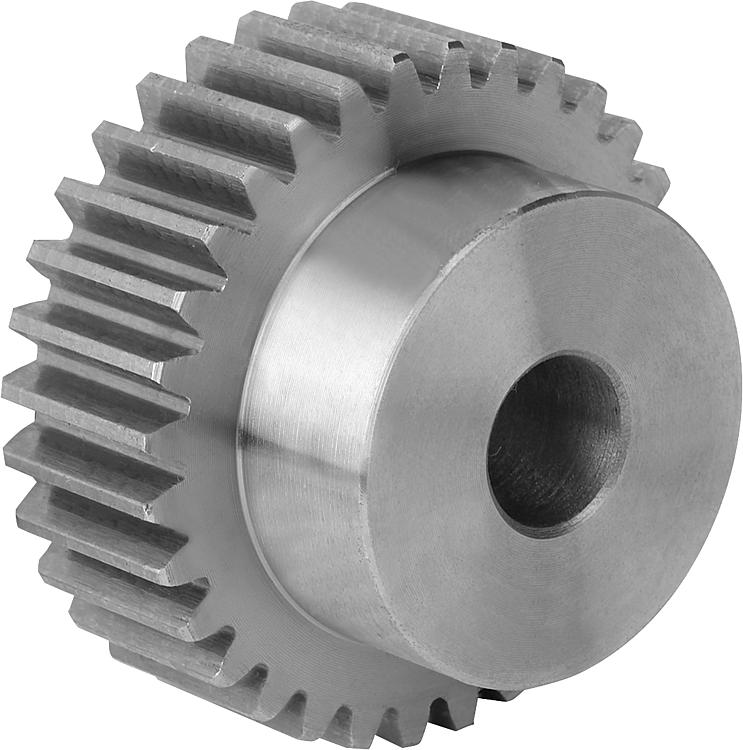
(i). Spur gears: The teeth are cut parallel to the axis of the shaft. Spur
gears are used, when the shafts are parallel.

(ii). Helical gears: The teeth of these gears are cut at an angle (β) with
the axis of the shaft. Helical gears impose radial and thrust loads on
the shafts. To eliminate the end thrust load, double helical gears are
used. These gears are called as Herringbone gears.


Gear for intersecting Shaft
(i) Bevel Gear: Bevel gears are used for shafts whose axes intersect each other. The angle can be 90 degree , less than 90 degree or more than 90 degree . The tooth of the bevel gears can be cut straight or spiral.

(a) Straight Bevel gears or Mitre Gears: When equal bevel gears (having equal teeth and equal pitch angles) connect two shafts whose axes intersect at right angle, then they are known as mitre gears.

(b) Angular Bevel Gears: When the bevel gears connect two shafts whose axes intersect at an angle other than a right angle, then they are known as angular bevel gears.
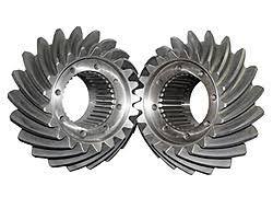
(c) Crown Bevel Gears: When the bevel gears connect two shafts whose axes intersect at an angle greater than a right angle and one of the bevel gears has a pitch angle of 90º, then it is known as a crown gear.

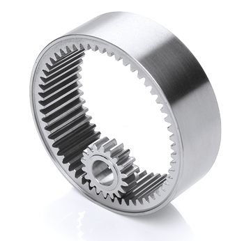
(d) Internal Bevel Gears: When the teeth on the bevel gear are cut on the inside of the pitch cone, then they are known as internal bevel gears.
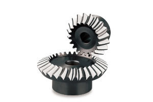
(e) Spiral Bevel Gears: In this bevel gears the teeth are curved & oblique. Such gears are run more quietly & take more load as compared to straight bevel gears.

(f) Zero Bevel Gears: These gears are similar to straight bevel gears but teeth are curved in the lengthwise direction. These teeth are arranged in such a manner that the effective spiral angle is zero.
Gear for non parallel or non intersecting shaft
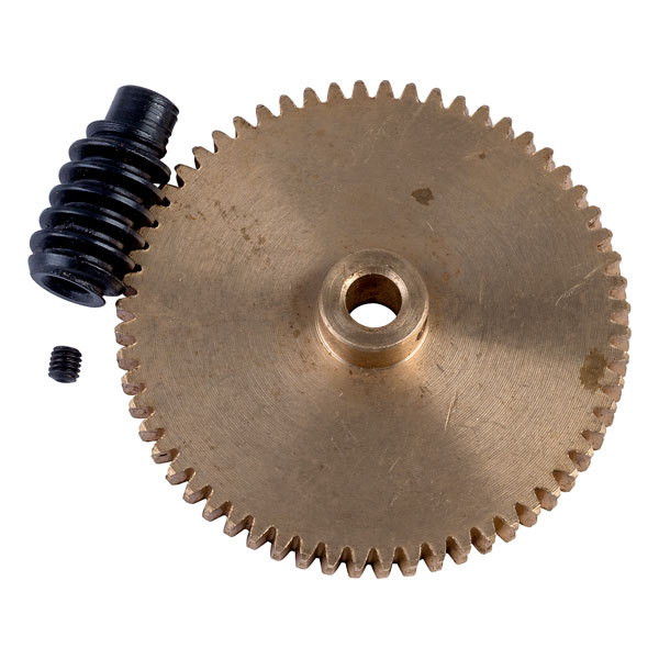
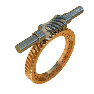
(i) Worm & Worm wheel: The worm gears are widely used for transmitting power at high velocity ratios between non-intersecting shafts that are generally, but not necessarily, at right angles. It can give velocity ratios as high as 300 : 1 or more in a single step in a minimum of space, but it has a lower efficiency. The worm gearing is mostly used as a speed reducer, which consists of worm and a worm wheel or gear.

Types of Worms
(a). Cylindrical or straight worm: The cylindrical or straight worm, is most commonly used. The shape of the thread is involute helicoid of pressure angle 14 ½° for single and double threaded worms and 20° for triple and quadruple threaded worms. The worm threads are cut by a straight sided milling cutter having its diameter not less than the outside diameter of worm or greater than 1.25 times the outside diameter of worm.
(b). Cone or double enveloping worm: The cone or double enveloping worm, is used to some extent, but it requires extremely accurate alignment.
Types of Worm Gears
(a). Straight face worm gear: The straight face worm gear is like a helical gear in which the straight teeth are cut with a form cutter. Since it has only point contact with the worm thread, therefore it is used for light service.
(b). Hobbed straight face worm gear: The hobbed straight face worm gear is also used for light service but its teeth are cut with a hob, after which the outer surface is turned.
(c). Concave face worm gear: The concave face worm gear is the accepted standard form and is used for all heavy service and general industrial uses. The teeth of this gear are cut with a hob of the same pitch diameter as the mating worm to increase the contact area.
(ii) Spiral Gears: These gear are also known as crossed helical gears. These gears are mounted on shaft that do not intersect & that are at an angle to each other. The angle is usually 90 degree.
(iii) Hypoid Gears: These gears are similar to Spiral bevel gears with the difference that the axis of shaft do not intersect.

2. According to peripheral velocity of the gears
(i) Low velocity: The gears having velocity less than 3 m/s are termed as low velocity gears.
(ii) Medium velocity: The gears having velocity between 3 and 15 m/s are known as medium velocity gears.
(iii) High velocity: If the velocity of gears is more than 15 m/s, then these are called high speed gears.
3. According to the type of gearing
(i) Internal Gearing: In internal gearing, the gears of the two shafts mesh
internally with each other.

(ii) External Gearing: In external gearing, the gears of the two shafts mesh externally with
each other.

(iii) Straight Gearing: Sometimes, the gear of a shaft meshes externally and internally with
the gears in a straight line, Such a type of gear is called rack and
pinion.

4. According to the position of teeth on the gear surface
(i) Straight teeth: When the teeth are cut on the gear parallel to axis of shaft. Example- Spur Gear
(ii) Inclined teeth: When the teeth are cut on the gear inclined to axis of shaft. Example- Helical Gear

(iii) Curved teeth: When the teeth are cut on the gear. Example- Spiral Bevel gear, Hypoid gear etc.



Comments
Post a Comment