Design of Spur Gear
Design of Spur Gear
Spur gears or straight-cut gears are the simplest type of gear. They consist of a cylinder or disk with teeth projecting radially. Though the teeth are not straight-sided (but usually of special form to achieve a constant drive ratio, mainly involute but less commonly cycloidal), the edge of each tooth is straight and aligned parallel to the axis of rotation. These gears mesh together correctly only if fitted to parallel shafts. No axial thrust is created by the tooth loads. Spur gears are excellent at moderate speeds but tend to be noisy at high speeds.

Design Procedure for Spur Gears
In order to design spur gears, the following procedure may be followed :
1. First of all, the design tangential tooth load is obtained from the power transmitted and the
pitch line velocity by using the following relation :
WT = (P/v) * Cs
where WT = Permissible tangential tooth load in newtons
P = Power transmitted in watts,
v = Pitch line velocity in m/s = [π D N / 60]
D = Pitch circle diameter in meters
N = Speed in r.p.m.
CS = Service factor.
The following table shows the values of service factor for different types of loads :
Types of Load
|
Type
of service
|
||
Intermittent or
3 hours
|
8-10 hours per day
|
Continuous 24
hours
per day
|
|
Steady Load
|
0.8
|
1.00
|
1.25
|
Light Shock
|
1.00
|
1.25
|
1.54
|
Medium Shock
|
1.25
|
1.54
|
1.80
|
Heavy Shock
|
1.54
|
1.80
|
2.00
|
2. Apply the Lewis equation as follows :
-
WT =
(σO× Cv) b.π m.y
Notes:
(i) The
Lewis equation is applied only to the weaker of the two wheels (i.e.
pinion or gear).
(ii) When
both the pinion and the gear are made of the same material, then pinion is the
weaker.
(iii) When
the pinion and the gear are made of different materials, then the product of (σw×
y) or (σo× y) is the *deciding factor. The
Lewis equation is used to that wheel for which (σw× y)
or (σo× y) is less.
3. Calculate the dynamic load (WD) on the tooth by using Buckingham equation, i.e.

Where

Where K = A factor depending upon the form of the teeth.
= 0.107, for 14.5° full depth involute system.
= 0.111, for 20° full depth involute system.
= 0.115 for 20° stub system.
EP = Young's modulus for the material of the pinion in N/mm2.
EG = Young's modulus for the material of gear in N/mm2.
e = Tooth error
action in mm. The maximum allowable tooth error in
action (e) depends upon the pitch line velocity (v) and the class
of cut of the gears.
Where the value of C find out from the tables-
Material
|
Involute teeth form
|
Values of deformation
factor (C) in N-mm
|
|||||
Pinion
|
Gear
|
Tooth error in action
(e) in mm
|
|||||
0.01
|
0.02
|
0.04
|
0.06
|
0.06
|
|||
Cast Iron
Steel
Steel
|
Cast Iron
Cast Iron
Steel
|
14 .50
|
55
76
110
|
110
152
220
|
220
304
440
|
330
456
660
|
440
608
880
|
Cast Iron
Steel
Steel
|
Cast Iron
Cast Iron
Steel
|
200 Full Depth
|
57
79
114
|
114
158
228
|
228
316
459
|
342
474
684
|
456
632
912
|
Cast Iron
Steel
Steel
|
Cast Iron
Cast Iron
Steel
|
200 Stub
|
59
81
119
|
118
162
238
|
236
324
476
|
354
486
714
|
472
648
952
|
Table- Values of maximum allowable tooth
error in action (e) verses pitch line velocity, for well cut commercial
gears
Pitch Line Velocity m/sec
|
Tooth error in action (e) mm
|
Pitch Line Velocity m/sec
|
Tooth error in action (e) mm
|
Pitch Line Velocity m/sec
|
Tooth error in action (e) mm
|
1.25
|
0.0925
|
8.75
|
0.0425
|
16.25
|
0.0200
|
2.5
|
0.0800
|
10
|
0.0375
|
17.5
|
0.0175
|
3.75
|
0.0700
|
11.25
|
0.0325
|
20
|
0.0150
|
5
|
0.0600
|
12.5
|
0.0300
|
22.5
|
0.0150
|
6.25
|
0.0525
|
13.75
|
0.0250
|
25 & above
|
0.0125
|
7.5
|
0.0475
|
15
|
0.0225
|
Table- Values of tooth error in action (e)
verses module
Module in mm
|
Tooth error in action
(e) in mm
|
||
First class commercial gears
|
Carefully Cut Gears
|
Precision gears
|
|
Up to 4
|
0.51
|
0.025
|
0.0125
|
5
|
0.055
|
0.028
|
0.015
|
6
|
0.065
|
0.032
|
0.017
|
7
|
0.071
|
0.035
|
0.0186
|
8
|
0.078
|
0.038
|
0.0198
|
9
|
0.085
|
0.042
|
0.021
|
10
|
0.089
|
0.0445
|
0.023
|
12
|
0.097
|
0.0487
|
0.0243
|
14
|
0.104
|
0.052
|
0.028
|
16
|
0.110
|
0.055
|
0.030
|
18
|
0.114
|
0.058
|
0.032
|
20
|
0.117
|
0.059
|
0.033
|
Note- In calculating the dynamic load (WD), the value of tangential load (WT) may be calculated by
neglecting the service factor (CS) i.e.
WT = P / v, where P is in watts and v in m/s.
4. Find the static tooth load (i.e. beam strength or the endurance strength of the tooth) by using
the relation-
WS = σe . b. π m. yP
For Safety WS> WD
The value of (σe) find from the following table-
Material of pinion
& gear
|
Brinell Hardness Number
(B.H.N)
|
Flexural endurance
gear (B.H.N.) limit (σe)
in MPa
|
Grey Cast Iron
|
160
|
84
|
Semi-Steel
|
200
|
126
|
Phosphor bronze
|
100
|
168
|
Steel
|
150
|
252
|
5. Finally, find the wear tooth load by using the relation,
Ww = DP .b.Q.K


Where Q find out from following formulas
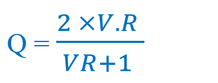
Where V.R = Velocity Ratio
K find out from following relationship-

Where Ep = Modulus of elasticity of Pinion.
EG = Modulus of elasticity of Gear.
The value of (σes) find from the following table-
Material of pinion
& gear
|
Brinell Hardness Number
(B.H.N)
|
Surface endurance
limit (σes) in MPa
|
Grey Cast Iron
|
160
|
630
|
Semi-Steel
|
200
|
630
|
Phosphor bronze
|
100
|
630
|
Steel
|
150
|
350
|
· The surface
endurance limit for steel may be obtained from the following equation :
σes
= (2.8 × B.H.N. – 70) N/mm2
The wear load (Ww) should not be less than the dynamic load (WD)
Numericals of Spur Gears- Click on Below Link-
Numericals of Spur Gear Design


Comments
Post a Comment