Steering System
Steering System
“The steering system allow the driver to guide the car along
the road & turn left or right as desired.”
The system includes the following:
1. The steering wheel
2. The steering gear
3. The steering linkage
The steering system configuration depends upon the
vehicle design (the drive train & suspension system
used).
Function of Steering System
1. The primary function of the steering system is to
achieve angular motion of the front wheels to
negotiate a turn.
2. To provide directional stability of the vehicle when
going straight ahead.
3. To minimize wear & tear of the tires.
4. To absorb a major part of the road shocks thereby
preventing them to get transmitted to the hands of
driver.
5. To provide perfect rolling motion of the road
wheels at all times.
Requirement of good steering system
1. Very accurate.
2. Easy to handle.
3. Provide directional stability.
4. Multiply the turning effort applied on the steering
wheel by the driver.
5. Irreversible to certain degree, so that the shock of
the road surface encountered by the wheels are not
transmitted to driver’s hands.
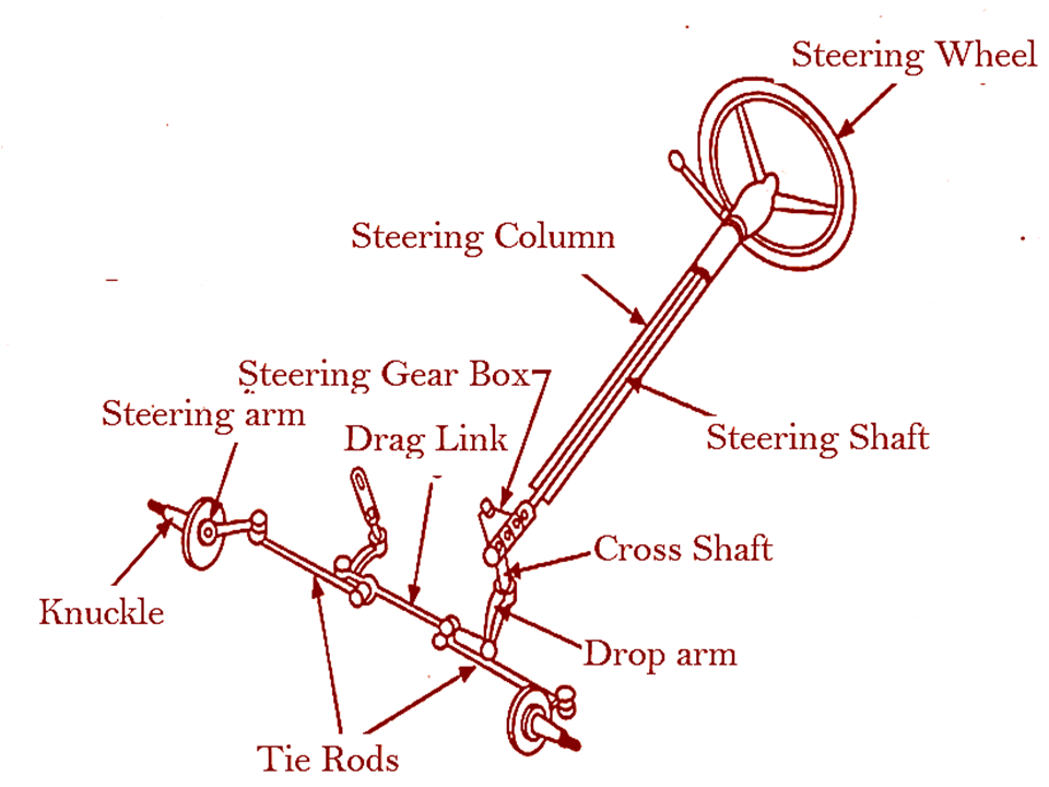
Parts of Steering System
The main parts of the steering system are:-
1. Steering Wheel
2. Steering Column
3. Steering Shaft
4. Steering Gear Box
5. Steering Drop Arm
6. Pull & Push Rod (Drag link)
7. Knuckle Arm
8. Tie Rod & Tie Rod End

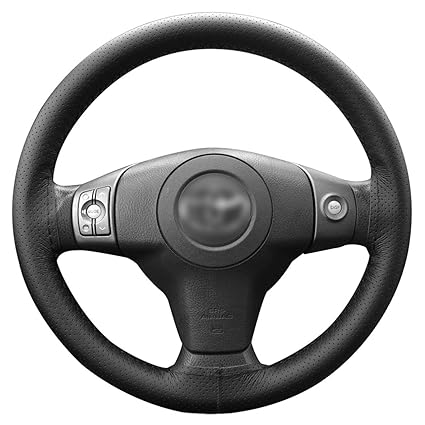
1. Steering Wheel :-
Its made of steel ring welded together on the hub with
the help of 2, 3 or 4 spokes. The steering wheel may be
fixed position or tilted position. The steering wheel is
pulled out with the help of puller.
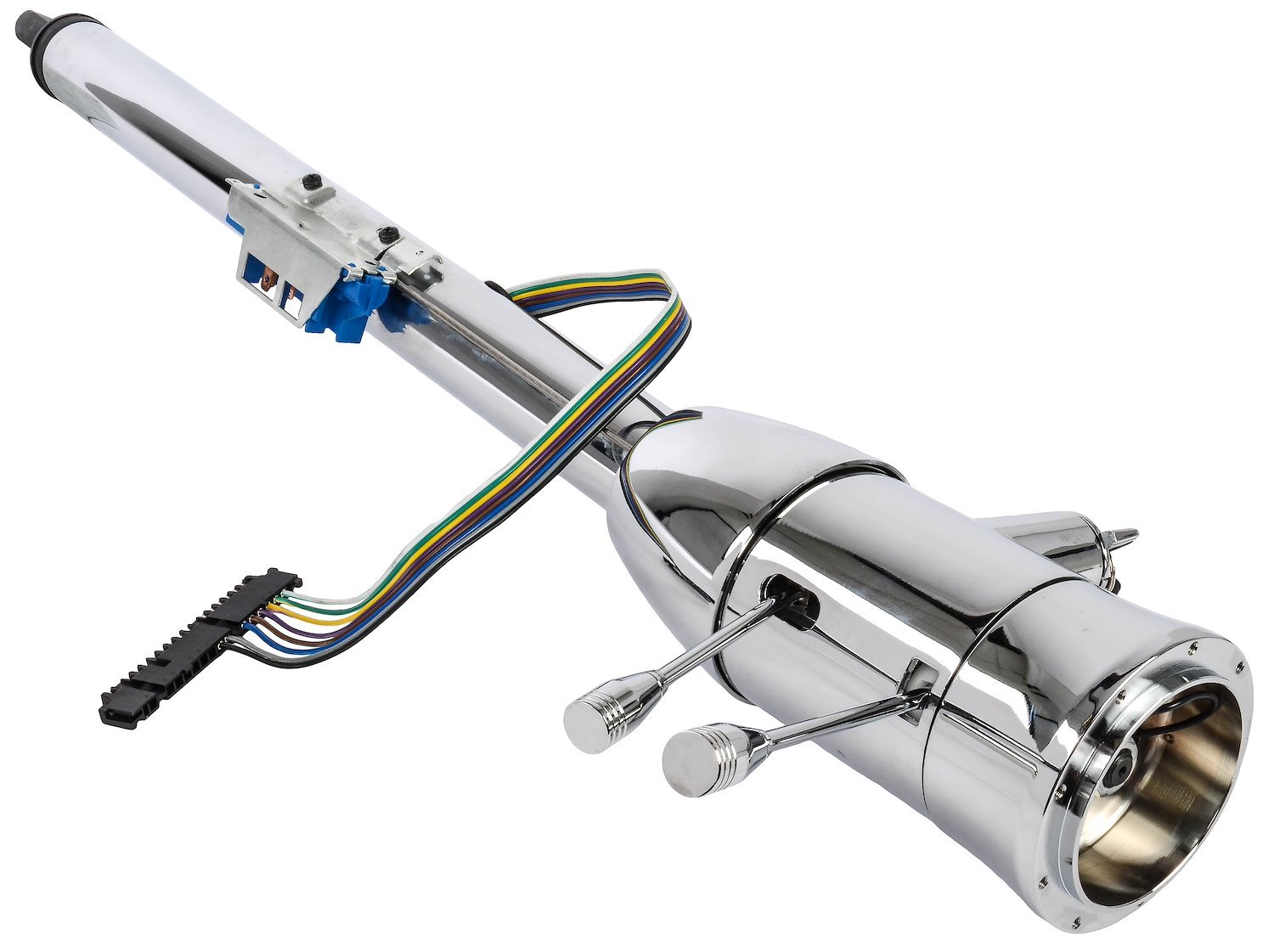
2. Steering Column:-
This is hollow steel pipe in which steering shaft is housed.
One end of the pipe is fixed into the steering box & other
end is usually held with the help of bracket under the
instrument panel.
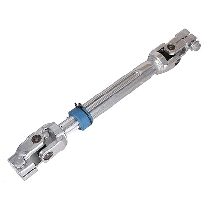
3. Steering Shaft:-
Its made of good quality steel.one end is fixed in the
steering wheel with the help of splines or key & kept tight
by nut. The other end with worm is secured in steering
box with the help of bearing placed both top & bottom.
4. Steering Gear Box:-
Its function to convert rotary motion of the wheel to-&-
fro motion of drop arm so that drag link tie up with drop
arm can pushed & pulled resulting into moving stub axle
to right or left as desired by driver.

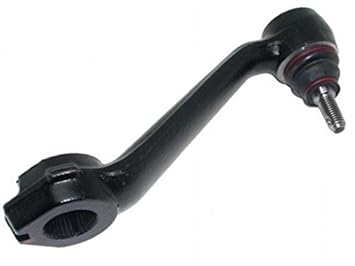
5. Drop arm:-
Its forged out of good quality steel. Its one side is
provided with splines which match the splines of sector
shaft & held on sector shaft by nut.
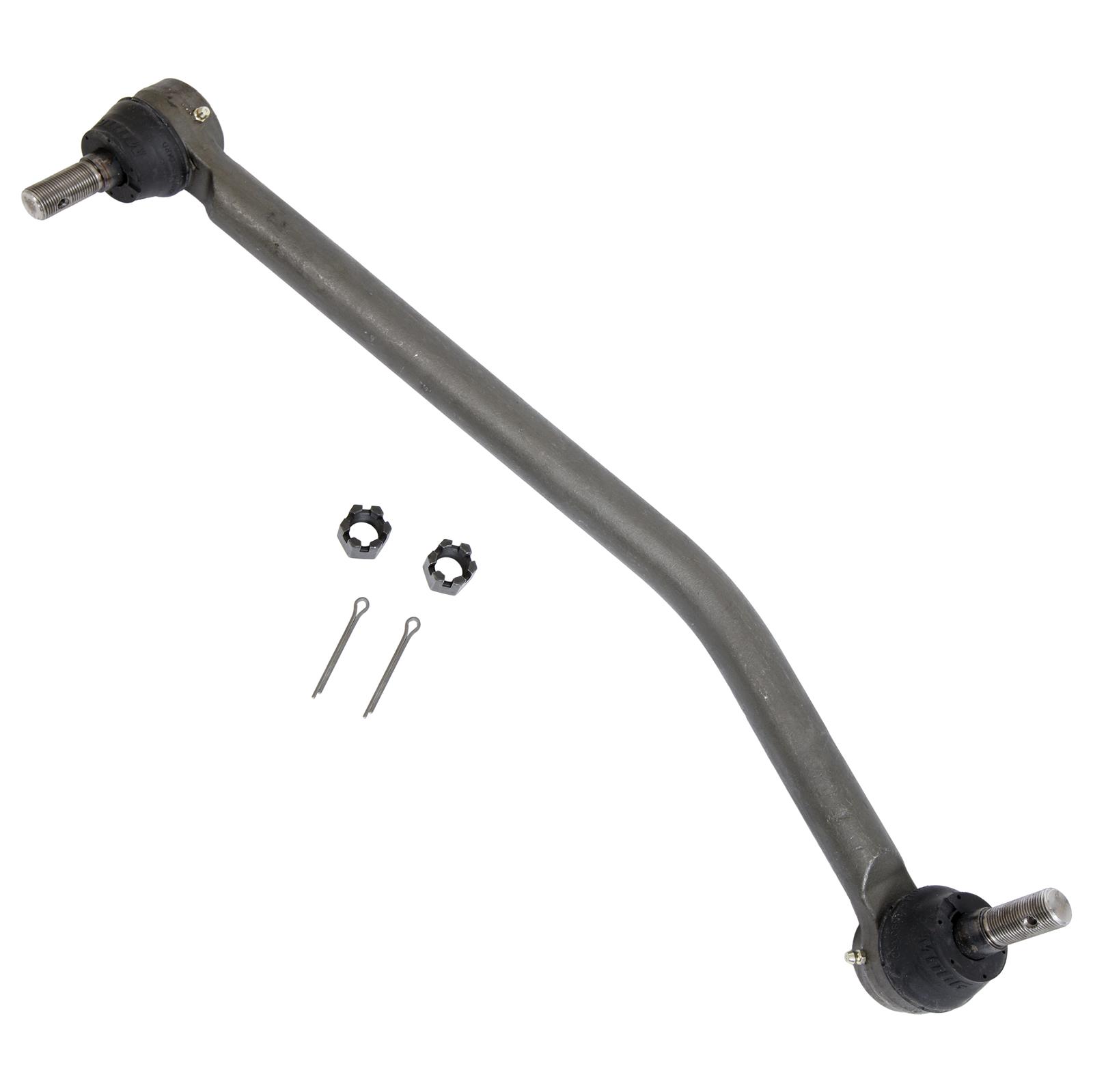
6. Pull & Push Rod (Drag link) :-
A drag link converts rotary motion from a crank arm, to a second bell crank, usually in an automotive steering system. one end of the drag link is connected via the Pitman arm and steering gearbox to the steering wheel (providing the connection between the driver and the steering system); the other end is attached to the steering linkage, by the steering arm.
7. Knuckle Arm :-
In automotive suspension, a steering knuckle is that part which contains the wheel hub or spindle, and attaches to the suspension and steering components. It is variously called a steering knuckle, spindle, upright or hub, as well.
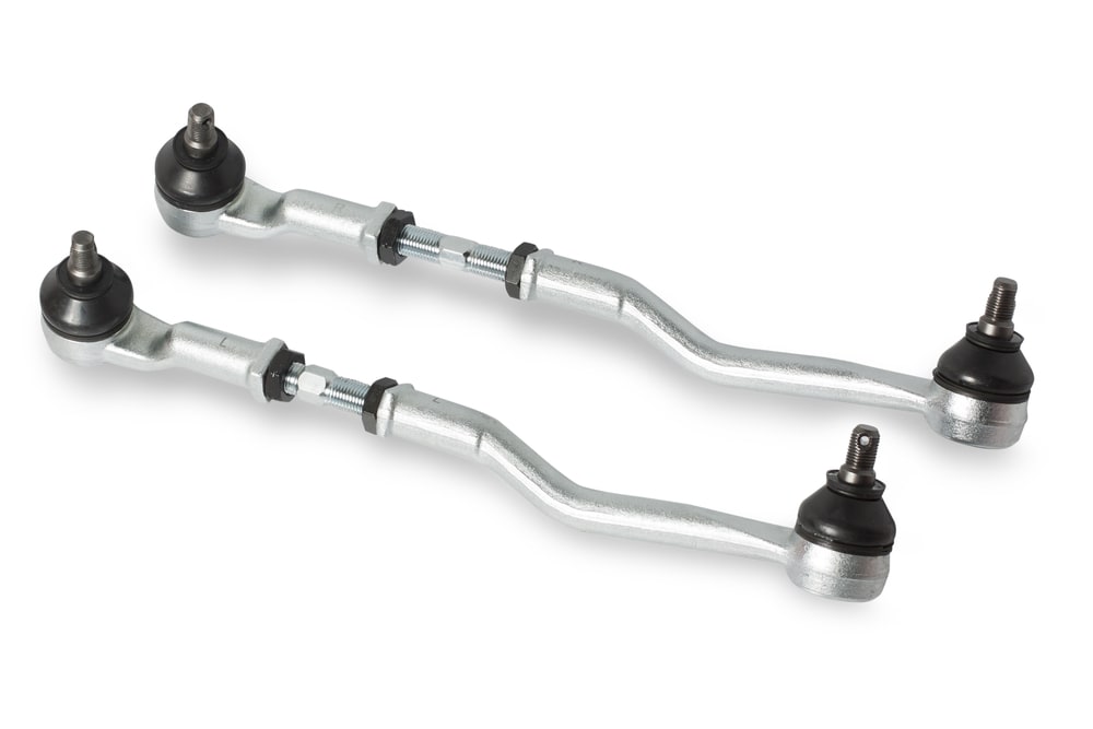
8. Tie Rod & Tie Rod End :-
The tie rod is a part of the steering mechanism in a vehicle. A tie rod consists of an inner and outer end. The tie rod transmits force from the steering center link or rack gear to the steering knuckle. This will cause the wheel to turn. The outer tie rod end connects with an adjusting sleeve, which allows the length of the tie rod to be adjustable. This adjustment is used to set a vehicle’s alignment angle.
Types of Steering Gear Box
The steering gear box are following types :-
1. Worm & worm wheel type
2. Worm & Nut type
3. Worm & roller type
4. Recirculating ball type
5. Rack & pinion type
6. Cam & lever type.
1. Worm & worm wheel type
In this type of steering gear box there will be worm at the bottom end of steering inner column. This worm meshes with a wheel in steering gear box housing. When steering wheel turned, the steering column revolves and the wheel is rotated along with it. This causes the drop arm to move and thereby drag link and other steering linkages like tie rods king pin etc. This steering commonly used in Tractor.

2. Worm & Nut type
In this type of steering gear box worm is an integral
part of steering column. Worm is mesh with a nut
arrangement. When worm rotate the nut is able to move. This
movement take place along the axis of the column
either up or down. This enable the cross shaft to rotate an arc. This in
turn helps the drop arm to also move in an arc. This
arm transmits the steering to all wheels.

3. Worm & roller type
In this steering gear, there will be a worm at the
bottom end of inner column and a roller is there in the
steering gear box. When the worm rotates, the roller which is attached to
it also rotates causing the roller to rotate and thereby
moving drop arm. This type of steering gear fitted in the Leyland vehicles
& American Passenger Cars.


4. Recirculating ball type
In this steering gear there will be some steel balls in
the grooves of steering inner column which move
along with the steering worm. This enables to control the friction among them and
there by reducing noise. It increases the mechanical
advantage of the operator for easy and smooth
operation of steering. This type of steering gears is used by Tata,
Dodge/Fargo & standard 20 vehicles.


5. Rack & pinion type
In this steering gear, a pinion is mounted at the end of
the steering inner column. It engages the rack which has ball joints at each end to
allow the raise and fall of the wheel, the rods are
connected with ball joint to the sub axles. The rotary movement of steering wheel turn the
pinion which moves the rack sideways parallel to tie
rod. This type of gears used in Maruti 800.


6. Cam & lever type
In this type of steering gear, a special worm called Cam
is located at the end of inner column which it attached
to column in the steering gear. When the worm is rotated, the lever is also moved in
the groove provided in the worm. This causes the lever
to swing through an arc.

Steering Ratio
“The steering ratio is number of degree that the steering wheel
must be turned to pivot the front wheel 1 degree.”
For example- if steering wheel must be turned 18 degree
to pivot the front wheels 1 degree. Therefore the steering
ratio is 18:1.
The steering ratio generally used with present day
steering gear vary from about 12:1 for small vehicle to
35:1 for heavy vehicle.
Wheel Alignment
“wheel alignment refer to the positioning of the front wheels &
steering mechanism that gives the vehicle directional stability,
promotes ease of steering & reduces tire wear to a minimum.”
The front wheel alignment depends upon the following
factors:-
1. Factor pertaining the steering geometry:-
1. Camber
2. King pin alignment
3. Caster
4.Toe-in
5. Toe-out
2. Factor pertaining to front wheel condition:-
1. Balance of wheel
2. inflation of tires
3. brake
adjustment
1. Factor pertaining the steering geometry:-
1. Camber
“Camber is tilting in & tilting out of the front wheels from the
vertical when viewed from the front of vehicle.”
If the top of the wheel is tilts out, it has “Positive camber". If the top of the wheel is tilts in, it has
“Negative Camber".
The amount of tilt measured in degree from the vertical, is
called “Camber Angle”.
The amount of camber, positive or negative, tends to
cause uneven or more tyre wear on one side than on the
other side. Its not exceed 2 degree.


2. King pin alignment
“The King pin inclination is the angle between the vertical line
& centre of the king pin or steering axle, when viewed from the
front of the vehicle.”
Its absolutely necessary due to following reasons:
1. It helps the car to have steering stability.
2. It make the operation of the steering quite easy
particularly when the vehicle is stationary.
3. It helps in reducing the wear on the tyres.
The combined camber & King pin inclination is called the
“Included angle.”
3. Caster
“The angle between the King pin centre line & the vertical, in
the plane of wheel is called Caster Angle.”
If the king pin centre line meets the ground at a point
ahead of the vertical centre line is called “Positive
Caster” while if its behind the vertical wheel centre line
is called “Negative Caster”.
The caster angle in the modern vehicles ranges from 2 degree to
8 degree .

4.Toe-in
“when the position of front wheels is less than the distance
between them at the rear. The front wheels point inward is
called Toe-in.”
The purpose of the toe-out is to give correct turning
alignment & to prevent excessive wear.


5. Toe-out
“when the distance between front wheels at the front end is
grater than the distance between them at the rear when the car
is stationary , this position of front wheels is called Toe-out.”
The Toe-in serves the following purpose.
1. It ensure parallel running of the front wheels.
2. It stabilizes steering.
3. It prevent the side slipping & excessive wear of the
tyres.
The Toe-in provides in the vehicles usually few
millimeters (3 to 5 mm).


Steering Mechanism
“The steering mechanism is used for changing the direction of
two or more of the wheel axles with reference to the chassis, so as
move the automobile in any desired path.”
The condition for the correct steering is that all the four
wheels must turn about the same instantaneous centre.
To avoid skidding the two front wheels must turn about
the same instantaneous centre which is lie on the axis of
rear wheels.
Let a= Wheel Track
b = Wheel Base
c = Distance between the pivot A & B of the front axle.
Now, from IBM
Cot θ = BM/IM
from IAM
Cot Ø = AM/IM
= (AB+BM)/IM
Cot Ø = (AB/IM) + (BM/IM)
Cot Ø= (c/b) + cot θ
Cot Ø – Cot θ = c/b
This is fundamental equation for correct Steering.
The turning circle radius for different wheels can also be
written
1. For the inner front wheel
RIF = b/Sin θ (a-c/2)
2. For the outer front wheel
ROF = b/Sin Ø + (a-c/2)
3. For the inner rear wheel
RIR = b/tan θ - (a-c/2)
4. For the outer rear wheel
ROR = b/tan Ø + (a-c/2)
Types of Steering Gear Mechanism
The steering gear mechanism are the following two
types:-
1. Davis steering gear
2. Ackermann steering gear

1. Davis steering gear:-
The Davis steering gear has
sliding pairs. Since sliding pair has more friction therefore
this type of gear will wear out earlier & become inaccurate
after sometime. Its theoretically correct.
It consists of cross link CD sliding parallel to another link
AB & is connected to the stub axles of the two front wheel by means of two similar bell crank levers LAC & MBD
pivoted at A & B.
The cross link CD slides in the bearing & carries pairs at
its ends C & D.
when the wheel is running straight the
gear is said to be in its mid position. The short arms AC &
BD are inclined at an angle (900 + a) to their stub axles
AL & BM.
The correct steering depends upon the suitable section of
cross arm angle a & is given by
tan a = c/ 2b
where c/b= 0.4 to 0.5
Where c= distance b/w the pivots of front axles.
b = wheel base.
Where a is lies between 11.3 to 14.1.

2. Ackermann steering gear:-
Its has turning pairs. Its
consists of cross link CD connected to the short axles AL &
BM of the two front wheels through the short arms AC &
BD forming bell crank lever LAC & MBD.
When the wheel is running straight, the cross link CD is
parallel to AB, the short arm AC & BD both makes angle a
to the horizontal axis of chassis.
Sin (a+ q) + Sin (a-Ø) = 2 sin a
For correct steering Cot Ø - Cot θ = c/ b
The value of c/ b lies between 0.4 to 0.555.
There are three values of θ which gives the correct steering
of the vehicles- 1st while turning right, 2nd
- while turning
left & 3rd -while in running straight.

Understeer & Oversteer
The angle through which the wheel has to turn sustain
the side force is called slip or Creep angle.
“when the slip angle of the front wheel is grater than the rear
wheel, the wheel turns at the radius larger than that intended &
the driver has to keep steering into turn. This condition is
known as Understeer.”
“When the slip angle of the rear wheel is grater than front wheel
the vehicle tends to Oversteer that is to turn into more than
driver indented.
“When the front & rear slip angles are the same neutral steer
occurs”

Advantages of Steering System
1. Better Steering Response – Your vehicle will respond faster to the steering that you perform overall. This allows your steering to be more precise and controllable on the road.
2. Cornering Stability – When you’re going around a corner in a vehicle, four-wheel steering will give you control and stability as you drive. This especially comes in handy if the road is wet.
3. Smaller Radius While Turning – Because you can turn the rear wheels in the opposite direction of the front wheels, this allows you to make smaller circular turns at lower speeds.
4. Better on Tougher Terrains – If you live in an area with a lot of dirt roads or possibly snowy roads in the winter, then you’ll want a vehicle with four-wheel steering to help you drive better on these difficult terrains.
5. Straight Line Stability – If you’re driving your vehicle down a straight road, the four-wheel steering will give you the best stability you could ever want. This helps when you have potholes and high winds within the environment.
6. Easy Lane Changing – If you’re traveling fast on the interstate and you need to change lanes quickly, you can easily do so with a four-wheel steering vehicle without having to turn the steering wheel too much.
Disadvantages of Steering System
1. Expensive – As great as four-wheel steering systems are, they also require many more components in their construction than two-wheel steering systems. Because of this, vehicles with four-wheel steering are more expensive.
2. Bigger Chance of Problems – Due to the fact that four-wheel steering systems have many components, especially electronic components, the entire system could become inoperable if just one of these components malfunctions. This means you’ll spend more time repairing or replacing components in a four-wheel steering system vehicle.


Comments
Post a Comment