Coupling
Coupling
"A coupling is a device used to connect two shafts together at their ends for the purpose of transmitting power."
The primary purpose of couplings is to join two pieces of rotating equipment while permitting some degree of misalignment or end movement or both. Shafts are usually available up to 7 metres length due to inconvenience in transport. In order to have a greater length, it becomes necessary to join two or more pieces of the shaft by means of a coupling.
Purpose of Coupling
Shaft couplings are used in machinery for several purposes.
1. To provide for the connection of shafts of units that are manufactured separately such as a motor and generator and to provide for disconnection
for repairs or alternations.
2. To provide for misalignment of the shafts or to introduce mechanical flexibility.
3. To reduce the transmission of shock loads from one shaft to another.
4. To introduce protection against overloads.
5. It should have no projecting parts.
Requirements of a Good Shaft Coupling
A good shaft coupling should have the following requirements :
1. It should be easy to connect or disconnect.
2. It should transmit the full power from one shaft to the other shaft without losses.
3. It should hold the shafts in perfect alignment.
4. It should reduce the transmission of shock loads from
one shaft to another shaft.
5. It should have no projecting parts.
Types of Shafts Couplings
Shaft couplings are divided into two main groups as follows
1. Rigid Coupling- It is used to connect two shafts which are perfectly aligned. Rigid coupling are following types.
(a) Sleeve or muff coupling
(b) Clamp or split-muff or compression coupling
(c) Flange coupling
1. Unprotected type flange coupling
2. Protected type flange coupling
3. Marine type flange coupling
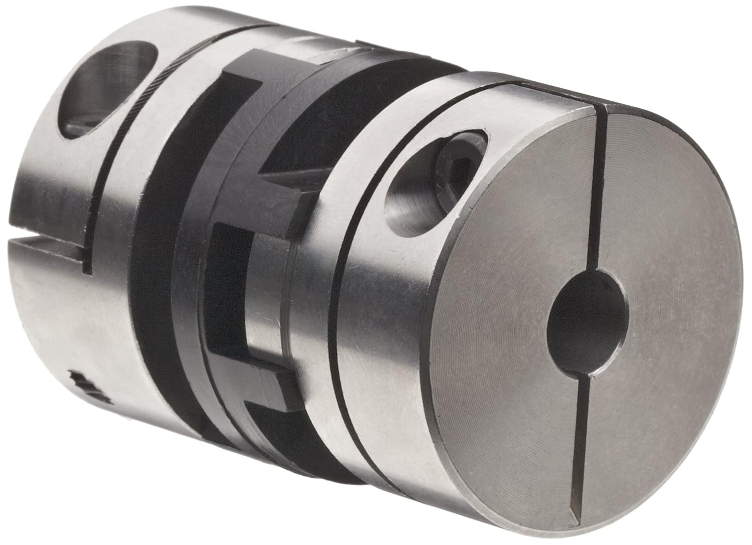
2. Flexible Coupling- It is used to connect two shafts having both lateral and angular misalignment. Flexible coupling are following types.
(a) Bushed pin type coupling
(b) Universal coupling
(c) Oldham coupling
Rigid Coupling
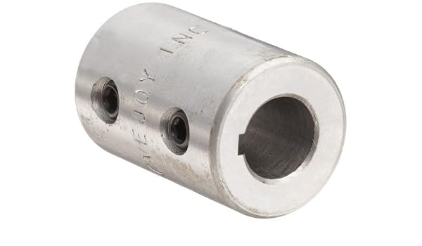
(a) Sleeve or Muff coupling
It is the simplest type of rigid coupling, made of cast iron. It consists of a hollow cylinder whose inner diameter is the same as that of the shaft. It is fitted over the ends of the two shafts by means of a gib-head key. The power is transmitted from one shaft to the other shaft by means of a key and a sleeve. It is, therefore, necessary that all the elements must be strong enough to transmit the torque.

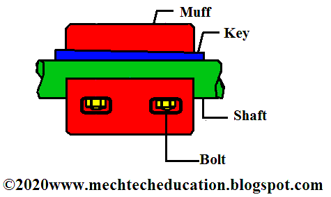
(b) Clamp or Split-muff or Compression coupling
It is also known as split muff coupling. In this case, the muff or sleeve is made into two halves and are bolted together. The halves of the muff are made of cast iron. The shaft ends are made to abut each other and a single key is fitted directly in the key-ways of both the shafts. One-half of the muff is fixed from below and the other half is placed from above. Both the halves are held together by means of mild steel studs or bolts and nuts. The number of bolts may be two, four or six. The nuts are recessed into the bodies of the muff castings. This coupling may be used for heavy duty and moderate speeds.

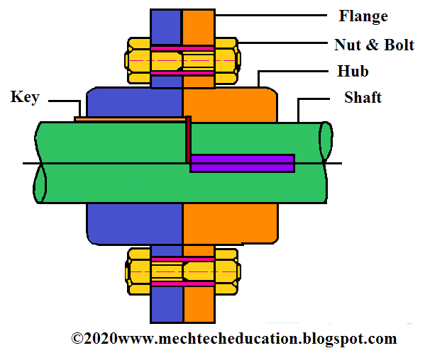
(c) Flange coupling
A flange coupling usually applies to a coupling having two separate cast iron flanges. Each
flange is mounted on the shaft end and keyed to it. The faces are turned up at right angle to the axis of the shaft. One of the flange has a projected portion and the other flange has a corresponding recess. The two flanges are coupled together by means of bolts and nuts. The flange coupling is adopted to heavy loads and hence it is used on large shafting. The flange couplings are of the following three types :
1. Unprotected type flange coupling.
2. Protected type flange coupling.
3. Marine type flange coupling.

1. Unprotected type flange coupling
In an unprotected type flange coupling each shaft is keyed to the boss of a flange with a counter sunk key and the flanges are coupled together by means of bolts. Generally, three, four or six bolts are used. The keys are staggered at right angle along the circumference of the shafts in order to divide the weakening effect caused by key-ways.
2. Protected type flange coupling
In a protected type flange coupling the protruding bolts and nuts are protected by flanges on the two halves of the coupling, in order to avoid danger to the workman.

3. Marine type flange coupling
In a marine type flange coupling, the flanges are forged integral with the shafts. The flanges are held together by means of tapered headless bolts, numbering from four to twelve depending upon the diameter of shaft.

The rigid flange couplings have the following advantages:
(i) Rigid coupling has high torque transmitting capacity.
(ii) Rigid coupling is easy to assemble and dismantle.
(iii) Rigid coupling has simple construction. It is easy to design and manufacture.
The rigid flange couplings have the following disadvantages:
(i) It is a rigid type of coupling. It cannot tolerate misalignment between the axes of two shafts.
(ii) It can be used only where the motion is free from shocks and vibrations.
(iii) It requires more radial space.
Flexible Coupling
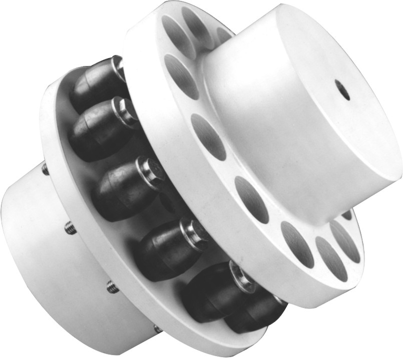
(a) Bushed pin type coupling
A bushed-pin flexible coupling is a modification of the rigid type of flange coupling. The coupling bolts are known as pins. The rubber or leather bushes are used over the pins. The two halves of the coupling are dissimilar in construction. A clearance provide between the face of the two halves of the coupling. There is no rigid connection between them and the drive takes place through the medium of the compressible rubber or leather bushes.

(b) Universal coupling
A universal or Hooke’s coupling is used to connect two shafts whose axes intersect at a small angle. The inclination of the two shafts may be constant, but in actual practice, it varies when the motion is transmitted from one shaft to another. The main application of the universal or Hooke’s coupling is found in the transmission from the gear box to the differential or back axle of the automobiles.

(c) Oldham coupling.
It is used to connect two parallel shafts whose axes are at a small distance apart. Two flanges, each having a rectangular slot, are keyed, one on each shaft. The two flanges are positioned such that, the slot in one is at right angle to the slot in the other. To make the coupling, a circular disc with two rectangular projections on either side and at right angle to each other, is placed between the two flanges. During motion, the central disc, while turning, slides in the slots of the flanges. Power transmission takes place between the shafts, because of the positive connection between the flanges and the central disc.


Comments
Post a Comment