Posts

TURBOJET ENGINE

Image
TURBOJET ENGINE The turbojet is an airbreathing jet engine, typically used in aircraft. It resembles the simplest form of gas turbine. It was separately coinvented by the two fathers of jet engines: Frank Whittle from Britain and von Ohain from Germany. The first airplane powered by a turbojet engine was the He178 German aircraft powered by the He S-3 engine on August 27, 1939. Types of Turbojet Engine 1. According to Power 1. Nuclear Turbojet Engine 2. Non-Nuclear Turbojet Engine 2. According to reused of exhaust gases 1. Afterburner Turbojet Engine 2. Non-afterburner Turbojet Engine 3. According to Spool 1. Single Spool (a) Axial flow compressor types (b) Centrifugal flow compressor types (i) Single entry types  (ii) Double entry types (c) Axial-Centrifugal flow compressor types 2. Double Spool Construction It consists of: 1. Diffuser. 2. Compressor. 3. Combustion chamber. 4. Turbine  5. Exhaust nozzle. 1. Diffuser - The function of the diffuser is to convert the kinetic energy of t

PULSE JET ENGINE (OR) FLYING BOMB

Image
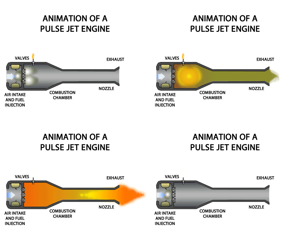
PULSE JET ENGINE (OR) FLYING BOMB A pulsejet engine (or pulse jet) is a type of jet engine in which combustion occurs in pulses. A pulsejet engine can be made with few or no moving parts, and is capable of running statically (i.e. it does not need to have air forced into its inlet, typically by forward motion). Pulsejet engines are a lightweight form of jet propulsion, but usually have a poor compression ratio, and hence give a low specific impulse. Types of Pulsejet Engine There are two types of pulsejet engine- 1. Valved Pulsejet Engine 2. Valveless Pulsejet Engine 1. Valved Pulsejet Engine Valved pulsejet engines use a mechanical valve to control the flow of expanding exhaust, forcing the hot gas to go out of the back of the engine through the tailpipe only, and allow fresh air and more fuel to enter through the intake as the inertia of the escaping exhaust creates a partial vacuum for a fraction of a second after each detonation. This draws in additional air and fuel between pulse

RAMJET ENGINE

Image
RAMJET ENGINE A ramjet is a type of athodyd (where athodyd stands for Aero THermODYnamic Duct ) airbreathing jet engine that was first proposed by Rene Lorin in 1913 . It uses the forward motion of engine to compress the incoming air, without a rotary compressor. Thus a ramjet is much like a valve less pulsejet but it operates with continuous combustion rather than the series of explosions that give a pulsejet its characteristic noise. The ramjet has been called a flying stovepipe, because it is open at both ends and has only fuel nozzles in the middle. Construction It consists of: 1. Supersonic diffuser 2. Subsonic diffuser 3. Combustion Chamber  4. Discharge nozzle  The function of supersonic and subsonic diffusers are to convert the kinetic energy of the entering air into pressure energy. This energy transformation is called ram effect and the pressure rise is called the ram pressure. The function of nozzle is to convert pressure energy of gas into kinetic energy. Working Air fr

JET PROPULSION

Image
JET PROPULSION "Jet propulsion is the propulsion of an object in one direction, produced by ejecting a jet of fluid in the opposite direction." The principle of Jet Propulsion is obtained from the application Newton's third law. i.e., For every action there is an equal  and opposite reaction. When a fluid is to be accelerated, a force is required to produce this acceleration in the fluid. At the same time, there is an equal and opposite reaction force acting on this fluid. This opposite reaction force of the fluid on the engine is known as thrust. Hence it may stated that the principle of jet propulsion is based on the reaction principle. Any fluid can be used to achieve the jet propulsion principle. Thus water, steam, and combustion gases are used to propel a body in a fluid. But there are limitations imposed upon the choice of the suitable fluid when it is applied to the propulsion bodies. CLASSIFICATION OF JET PROPULSION Jet Propulsion engines may be classified broadl

ROCKET STAGING

Image
 ROCKET STAGING All rockets use the thrust generated by a propulsion system to overcome the weight of the rocket. For full scale satellite launchers, the weight of the payload is only a small portion of the lift-off weight. Most of the weight of the rocket is the weight of the propellants. As the propellants are burned off during powered ascent, a larger proportion of the weight of the vehicle becomes the near-empty tankage and structure that was required when the vehicle was fully loaded. In order to lighten the weight of the vehicle to achieve orbital velocity, most launchers discard a portion of the vehicle in a process called staging.  Types of Staging- There are two types of rocket staging- 1. Serial Staging 2. Parallel Staging. 1. Serial Staging In serial staging (sometimes identified as tandem or vertical staging), the first stage is at the bottom and is usually the largest; the second stage and subsequent upper stages are above it, usually decreasing in size. The first-stage en

ELECTRICAL ROCKET ENGINES

Image
ELECTRICAL ROCKET ENGINES Electric propulsion engines generate exhaust velocities from about 4 to more than 100 times those of chemical rocket engines. There are three basic types of electrical rocket engines. They are : 1. Arc plasma rocket engine 2. Ion rocket engine 3. Magneto-plasma rocket engine 1. ARC PLASMA ROCKET ENGINE It is one of the simplest types of electrical rocket engines. It consists of: (1) Propellant tank (2) Combustion chamber (or) thrust chamber (3) Cooling system (4) Electric power supply The combustion chamber (or) thrust chamber contains two electrodes. The nozzle walls serve as the cathode, and an electrode within the chamber is serve as the anode. Liquid fuel from the propellant tank is pumped to a thrust chamber. When electric power supply is given, an arc is formed between cathode and anode. When the propellant is passing through the arc, an electrically neutral plasma gases (ionized gases) are produced. The highly heated plasma gases are then allowed to ex

NUCLEAR ROCKET ENGINE

Image
NUCLEAR ROCKET ENGINE In nuclear rocket, nuclear energy is used to heat the propellant or working fluid to get high temperature in the combustion chamber. Liquid hydrogen is widely used as a propellant. The combustion chamber consists of nuclear fission reactor, reflector, moderator, control rods, etc. Parts of Nuclear Rocket Engine 1. Nuclear Reactor It is an apparatus in which heat is produced due nuclear fission chain reaction. Nuclear reactors are used at nuclear power plants for electricity generation, propulsion of ships and also in nuclear thermal Rocket Propulsion system. Components of Nuclear reactor 1. Reflector - Reflects neutrons produced in the reaction back into the core. It's Prevents neutron leakage & maintains reaction balance. 2. Shielding - Shielding is required to protect the working men from the harmful effects of the radiation. 3. Moderator - To slow down neutrons from high velocities and hence high energy level which they have on being released from fis

HYBRID PROPELLANT ROCKET ENGINE

Image
HYBRID PROPELLANT ROCKET ENGINE The hybrid rocket engines combine the advantages of both solid and liquid propellant rockets. In this type, solid fuel along with liquid oxidizer is used as a propellant. Solid fuel is packed in the combustion chamber and the liquid oxidizer is stored in the separate tank. Working The liquid oxidizer which is stored in the separate tank is injected into the combustion chamber. When liquid oxidizer mixes with solid fuel in the combustion chamber, combustion takes place automatically. When the combustion takes place in the combustion chamber, very high pressure and very high temperature gases are produced. The highly heated products of combustion gases are then allowed to expand in the nozzle section. In the nozzle, pressure energy of the gas is converted into kinetic energy. So the gases coming out from the unit with very high velocity. Due to high velocity of gases coming out from the unit, a force (or) thrust is produced in the opposite direction. This

SOLID PROPELLANT ROCKET ENGINE

Image
SOLID PROPELLANT ROCKET ENGINE A solid propellant rocker engine Solid propellant is the combination of solid fuel (plastic or resin material) and oxidizer (nitrates, perchlorates, etc.) Solid fuel and oxidizer are homogeneously mixed and packed inside the shell. A liner is provided between the shell and the propellant. The purpose of liner is to protect the shell because high temperature will be generated during combustion process.  Working  In solid propellant rocker engine   the igniter located at the top and ignites the spark. So combustion takes place. When the combustion takes place in the combustion chamber, very high pressure and very high temperature gases are produced The highly heated products of combustion gases are then allowed to expand in the nozzle section. In the nozzle pressure energy of the gas is converted into kinetic energy. So the gases coming out from the unit with very high velocity. Due to high velocity of gases coming out from the unit, a force (or) thrust is

LIQUID PROPELLANT FEED SYSTEM

Image
 LIQUID PROPELLANT FEED SYSTEM There are two types of liquid feed system. They are : (1) Gas pressure feed system (2) Pump feed system 1. GAS PRESSURE FEED SYSTEM In the gas pressure feed system an inert gas (Helium or Nitrogen) is stored in a tank at high pressure and it is passed into pressure-regulator valves. This high pressure inert gas from the regulator is used to force the propellants (Fuel and Oxidizer). The propellants under high pressure are forced to flow into the combustion chamber through control valves. Several regulating and check valves are used for filling, draining and checking the flow of propellants. Moving parts such as pumps and turbines are not used. Therefore, this system is considerably simpler. The pressurization of the propellant tank is comparatively much heavier. So, this system is not suitable for large rocket engines and long range missions. 2. TURBO PUMP FEED SYSTEM In this system, liquid fuel and the liquid oxidizer are stored in a separate tank at low