Braking System
Braking System
“Braking system is an arrangement of various linkages and components (brake lines or mechanical linkages, brake drum or brake disc , master cylinder or fulcrums etc.) that are arranged in such a fashion that it converts the vehicle’s kinetic energy into the heat energy which in turn stops or de accelerate the vehicle.”
The conversion of kinetic energy into heat energy is a function of frictional force generated by the frictional contact between brake shoes and moving drum or disc of a braking system.
Need of Braking System
In an automobile vehicle braking system is needed –
1. To stop the moving vehicle.
2. To de accelerate the moving vehicle.
3. For stable parking of a vehicle either on a flat surface or on a slope.
4. As a precaution for accidents.
5. To prevent the vehicle from any damage due to road conditions.
Classification of Braking System
(i) Mechanical braking system
(ii) Hydraulic braking system
(iii) Air or pneumatic braking system
(iv) Vacuum braking system
(v) Electric braking system
2. On the Basis of Frictional Braking Contact
(i) Internal expanding brakes (e.g.- drum brakes)
(ii) External contracting brakes(e.g. disc brakes)
(ii) Hydraulic braking system
(iii) Air or pneumatic braking system
(iv) Vacuum braking system
(v) Electric braking system
2. On the Basis of Frictional Braking Contact
(i) Internal expanding brakes (e.g.- drum brakes)
(ii) External contracting brakes(e.g. disc brakes)
(i) Foot or service brakes
(ii) Hand or parking brakes
4. On the Basis of Brake Force Distribution
(i) Single acting brakes
(ii) Dual acting brakes
Mechanical Braking System
“The brakes which are operated mechanically by means of
levers, linkages, pedals, cams, bell cranks etc. are known as
Mechanical Brakes.”
Mechanical brakes all act by generating frictional forces as
two surfaces rub against each other. The stopping power
or capacity of a brake depends largely on the surface area
of frictional surfaces as well as on the actuation force
applied.
The mechanical brakes are generally Three Types:-
1. Internal Expanding Brake (Drum Brake)
2. External Expanding Brake (Disc Brake)
3. Hand Brake (Parking Brake)
1. Internal Expanding Brake (Drum Brake)
The whole assembly of the drum brake is fitted to the back
plate of the wheel. The back plate remains stationary and it
does not rotates with the wheel.
1. Brake Drum:
It is a round cast iron housing which is used to stop the
vehicle with the help of brake shoe. The drum brake is
bolted to the hub of the wheel. It rotates with the hub.
2. Brake Shoe:
It is the frictional part of the drum brake, without it the
working of the brake is not possible. The brake shoe has
brake lining at its outer curve. It is the brake lining which
makes contact with brake drum during the stopping of the vehicle.
It is of two types-
1.Primary brake Shoe: The shoe
having large lining material is called as primary shoe.
2.Secondary brake shoe: The shoe with small lining material is
called secondary shoe.
3. Wheel Cylinder:
It is used to force the brake shoe outward to apply the brake.
The wheel cylinder is connected to the master cylinder. It
contains piston which moves outward when brake is applied
and forces the brake shoe towards inner surface of the drum.
4. Return or Retracting Spring:
It is used to retract the brake shoe after brake is applied.
Two return springs are there in drum brake, one for the
primary shoe and other one is for secondary shoe.
5. Self Adjuster:
It maintain the minimum gap between the brake shoe and
drum so that they do not contact each other when pedal is
not pressed. In the case if the brake lining wear out, and gap
increases in between the shoe and drum, It can be adjusted
again to maintain the gap between shoe and drum inner
surface. once it is adjusted it maintains the same gab during
the brake working by itself.
Working of Internal Expanding Brake
- As the brake pedal is pressed, it compresses the fluid in the master cylinder and allows the piston of the wheel cylinder to expand outward.
- The outward motion of the piston of wheel cylinder forces the brake shoe outward against the brake drum.
- As the brake shoe lining touches the inner surface of the drum, and due to the friction generated in between the brake shoe and drum, the motion of the wheel reduces and vehicle stops.
- As the force is removed from the brake pedal, the retracting springs draws the brake shoe inward and the contact between the friction lining and drum ended. Now again the brake is ready to apply.
- A self adjusting screw is present at the bottom, which is used to maintain a minimum gap between the drum and brake shoe. When the lining of the brake shoe is wear out than the gap between the drum and brake shoe increases, at that time the adjuster is adjusted again to maintain the minimum gap.

Advantages of Internal Expanding Brake
1. They are self energizing braking system. It means they
are designed to operate by itself.
2. It is cheaper than the disc braking system.
Disadvantages of Internal Expanding Brake
1. Heating problem
2. The drum brakes will not work properly if it gets wet in
water.
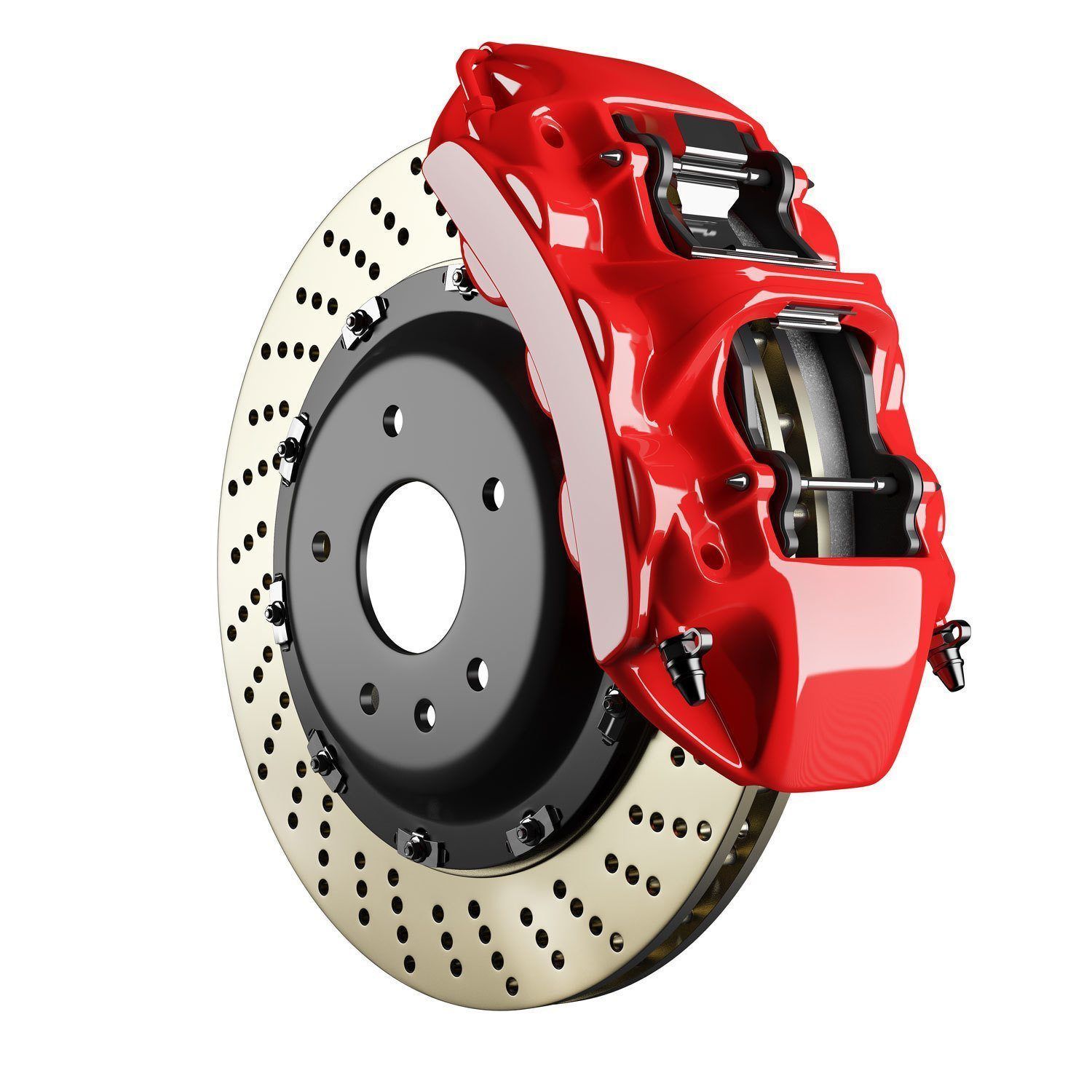
2. External Expanding Brake (Disc Brake)
1.Wheel Hub:
The disc rotor is attached to the wheel hub
and it rotates with it. The wheel of the vehicle is bolted to
the wheel hub.
2. Caliper Assembly:
The caliper assembly consist of
1. Brake pad: It makes contact with the rotor disc and due to
the friction between the brake pad and rotor disc the vehicle
speed reduces and it stops.
2. Caliper bracket
3. Caliper frame
4. Piston: It applies the brake force on the brake pads when
brake lever is pressed.
3. Disc Rotor: It is the rotating part of disc brake. When
brakes are applied, a lot of heat is generated which can
decrease the braking efficiency, so the rotor has drilled vent
holes on it which dissipates the heat.

Working of External Expanding Brake
- When brake pedal is pressed, the high pressure fluid from the master cylinder pushes the piston outward.
- The piston pushes the brake pad against the rotating disc.
- As the inner brake pad touches rotor, the fluid pressure exerts further force and the caliper moves inward and pulls the outward brake pad towards the rotating disc and it touches the disc.
- Now both the brake pads are pushes the rotating disc, a large amount of friction is generated in between the pads and rotating disc and slows down the vehicle and finally let it stop.
- When brake pad is released, the piston moves inward, the brake pad away from the rotating disc. And the vehicle again starts to move.

Advantages of External Expanding Brake
1. It is lighter than drum brakes.
2. It has better cooling (because the braking surface is
directly exposed to the air).
3. It offers better resistance to fade.
4. It provides uniform pressure distribution
5. Replacement of brake pads are easy.
6. By design they are self-adjusting brakes.
Disadvantages of External Expanding Brake
1. It is costlier than drum brakes.
2. No servo action is present.
3. It is difficult to attach a suitable parking attachment.
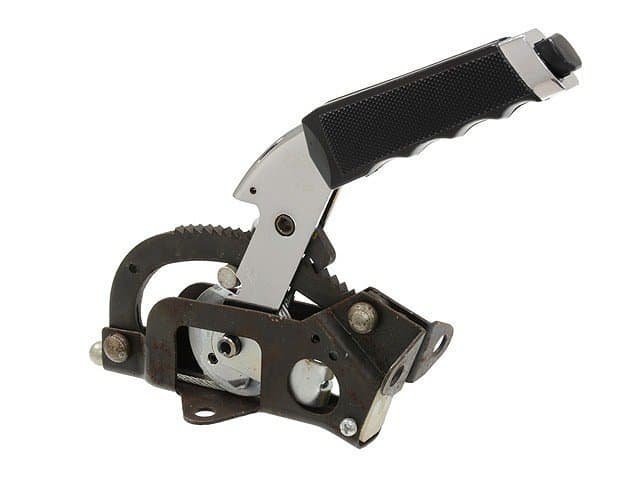
3. Hand Brake (Parking Brake)
Hand brake are usually the mechanical brakes. These brake
independently of the foot brakes. These are used for parking
on slopes & during emergency & also called secondary brakes.
Hand brakes are generally located on the side of the driver’s
seat. On most of the vehicles Hand brakes are applies on he
rear wheels.
In order to apply the brakes the ratchet is released first by
pressing the ratchet release handle, which cause the pawl to
move up, disengaging the ratchet. Then the brake lever
pulled up, while further pulls the cable which in them
operated the rear brakes mechanically through a linkage Operating on the piston of the rear wheel cylinder, which is
two halves.
The ratchet release handle which had been pressed so which
had been pressed so far is released now, so that the pawl
moves down the spring action & engages with the ratchet
thus keeping the brakes applied.

Hydraulic Brake System
“Brakes which are operated by means of hydraulic pressure are
known as Hydraulic brakes.”
In hydraulic system when the brakes are applied, the
pressure is increase sufficiently in the system to produce
equal & uniform braking action on the all four wheels. The
hydraulic brakes function based on the principle of Pascal’s
law which state as follow:-
“Pressure applied to a liquid is transmitted equally in all
directions.”
Main parts of hydraulic brakes:
1. Master cylinder:
It is the main part is the whole assembly. It works as a
hydraulic actuator which has a piston-cylinder arrangement.
It is responsible for the conversion of mechanical force into
the hydraulic force. As the brake pedal is pressed the fluid in
the master cylinder compressed and exerts pressure which is
transmitted to Brake assembly through the hydraulic lines.
2. Brake pedal and mechanical linkage:
Brake Pedal pressed manually when we have to stop or slow
down the running body. It is further attached with little
mechanical linkage such as spring which helps in retraction
of the pedal further it connects to master cylinder.
3. Hydraulic/brake fluid reservoir:
It is kind of a small tank for the braking fluid. It is directly
attached to the master cylinder. Sometimes due to small
leakages the level of fluid goes down into the master
cylinder so to maintain the proper amount of brake fluid in
the working operation a reservoir is required.
4. Hydraulic lines:
Hydraulic lines are the connections between the various
components of the braking system. Braking fluid travels
through these lines from master cylinder to brake. These are
the small diameter pipes which replace the different types of
mechanical linkage in case of mechanical brakes.
5. Brake fluids:
The common brake fluids which are used for the hydraulic
brakes are DOT3, DOT4, DOT5, etc. For instance, DOT3
DOT4 and DOT5 are glycol ether based which generally
means that they absorb moisture from the atmosphere.
Working of Hydraulic Brake
The brake pedal is connected to the master cylinder piston
by means of a piston rod. When the brakes are applied or when the brake pedal is
pressed, the piston is forced into the master cylinder, which
increases the pressure of the fluid in the master cylinder and
in the entire hydraulic system. This pressure is conducted instantaneously to the wheel
cylinders on each of the four brakes, where it forces the
wheel cylinder pistons outwards. These pistons, in turn, force the brake shoes out against the
brake drums. Hence, brakes are applied When the brake pedal is released, the master cylinder piston
returns to its original position due to the return spring
pressure. The fluid pressure in the entire system drops to its original
low value, which allows retracting springs on wheel brakes
to pull the brake shoes out of contact with the brake drums
into their original positions. This causes the wheel cylinder pistons also come back to
their original inward position. Thus, the brakes are released.

Master Cylinder
In hydraulic braking system, master cylinder is a device that
provides required amount of pressure or braking force to the final
braking components after multiplication of the mechanical force
applied by the driver through brake pedal or brake lever.
Types of Master Cylinder
1. Single Master Cylinder
2. Tandem Master Cylinder or Dual Master Cylinder
1. Single Master Cylinder:-
It is the simple type of master cylinder just like a medical
syringe, in this type of master cylinder single piston inside a
cylinder is used to cause braking. Single master cylinder distributes equal force in all the
wheels due to the use of single cylinder single piston or
circuit.
In single circuit master cylinder when brake pedal is not
pressed i.e. non actuation position the piston remains at its
original position which in turn closes the inlet valve of the
reservoir due to which there is no incoming of brake fluid
takes place between reservoir to compression chamber.
When brake pedal is pressed i.e. actuated position, the piston
which is connected to the brake pedal through connecting
rod moves which in turn opens the inlet valve due to which
incoming of brake fluid from reservoir to compression
chamber takes place. This brake fluid inside the compression chamber is
compressed due to the movement of piston inside the
cylinder just like the medical syringe.
After compression up to a certain pressure the outlet valve
opens and this highly compressed brake fluid is further
transferred to the brake lines for further brake actuation.

2. Tandem Master Cylinder or Dual Master Cylinder:-
It is the modified type of master cylinder in which dual
cylinder-dual piston or single cylinder dual piston along
with dual circuit is used for independent braking between
front and rear wheels.
This type of master cylinder is used in almost all cars as it
is more efficient than single circuit master cylinder. When brake pedal is not actuated, the piston remains at
their original place, closing the inlet valve of both the
compression chambers, which in turn cuts the incoming
of brake fluid between both the reservoir or both the
reservoir chambers. When the brake pedal is actuated, at first the primary piston
moves due to which opening of primary inlet valve takes
place. Initially due to the movement of primary piston
compression of the brake fluid inside primary chamber
takes place. After completion of the compression in primary chamber
primary outlet valve opens up and this compressed brake
fluid is further sent to brake calipers through brake lines
and actuation of the primary circuit brakes take place.
After the completion of the primary piston movement i.e.
at its extreme end, the secondary piston starts moving
because of the force applied by the primary piston’s
spring which in turn opens the secondary valve and
incoming of brake fluid from secondary reservoir to
secondary compression chamber takes place. This brake fluid is then compressed and after complete
compression secondary outlet opens up and this highly
compressed fluid is sent to the brake calipers through
brake lines and actuation of the secondary circuit brakes
take place.

Advantages of Hydraulic Brake System
1. They transmit uniform pressure. (Due to hydrostatic
pressure being equal in all directions, Pascal law).
2. They help in multiplying the driver’s effort more times
than that of Mechanical Brakes. (Hydraulic leverage ratio,
hydraulic advantage). Higher mechanical advantage.
3. The brake fluid also acts as a lubricant and reduce the
frictional losses at high-speed braking.
4. They are simpler in construction and lighter in weight.
5. Thermal stresses generated are much lower in hydraulic
brakes than Mechanical Brakes.
6. They are more wear resistant.
Disadvantages of Hydraulic Brake System
1. There is always a possibility of oil/fluid leakage which
can render the system inoperative or compromise the
friction surfaces.
2. Extreme heat may cause the fluid to boil forming gas
bubbles which compress and can’t transmit pressure
effectively.
3. However, Environmental factors such as moisture can
deteriorate the hydraulic fluid over time and cause
corrosion/failure of internal components.
Pneumatic Brake System
“Brakes which are operated by means of air pressure are known as
air brakes.”
Air brakes are also known as pneumatic brakes.
The first air brake was invented by George Westinghouse, he
introduced this type of brake for the use in trains.
Air brakes are widely used in heavy vehicles like trucks and
buses because they are heavy in weight and they need more
effort on brake pedal to stop them, and for comfortably
braking them air brake is good as it has high potential
energy and does not requires much effort to push the brake
pedal.
Parts of Pneumatic Brake System
The main components of Air brakes are as follows:
1. Filter:
It is a filter which filters the air by removing or
blocking any dust particles and allow clean air to the system.
The filtered air is sent to the air compressor.
2. Compressor:
It takes air through filter. It then compresses
air.
3. Reservoir:
It stores compressed air which is used for the
braking system.
4. Unloader valve:
It is situated at compressor. It opens when
the compressor pressure switch trips to OFF position.
5. Brake valve:
It opens when the brakes are applied by
extending lines of tubing.
Working of Pneumatic Brake System
Firstly, the compressor takes air from the atmosphere
through a filter. Then air filter, filters the air sends it to the
compressor where it gets compressed. Then this compressed
air is sent to the reservoir through the unloader valve, which
opens itself at a predefined reservoir pressure and are
connected to the brake valve. The lines of tubing from the
brake valve extend to the front and rear brake chambers. The air is supplied to brake chambers placed at each
wheels, through the brake valve. This brake valve is
controlled by the driver who can control the intensity of
braking according to the requirement.
When the brake pedal is pressed, pressure in the reservoir
drops which then pushes the brake pad against the brake
drum and the braking action occurs and the vehicle slows
down or stops according to the pressure applied. When the brake pedal is released the unloader valve gets
closed and there is no pressure on brake pads. Additionally, the compressed air available on the vehicle is
also used for the operation of additional assemblies of the
vehicle like horn, windshield wipers, etc.

Advantages of Pneumatic Brake System
1. The air braking system is cleaner.
2. Air is freely available so no cost for air.
3. Ease of use and maintenance.
4. Safe and explosion proof.
5. Reserved compressed air can be stored for afterwards
usage.
Disadvantages of Pneumatic Brake System
1. The air can leak very easily.
2. When the air brakes are applied there is some kind of
noise produced due to air. The noise is also produced while
changing pressure from the compressor.
3. It does not work underwater and under extreme
temperature.
Vacuum Brake System
“Brakes which are operated by means of Vacuum are known as
Vacuum brakes.”
Vacuum brake refers to the braking system that utilize
suction from engine inlet manifold for brake application.
The braking force are provided by the pressure difference that exits
on the opposite side of a piston or diaphragm that operated in
cylinder.

Types of Vacuum Brake System
The vacuum brake are generally two types:-
1. Atmospheric suspended vacuum brake
2. Vacuum suspended vacuum brake
1. Atmospheric suspended vacuum brake
Its consists of a piston cylinder arrangement in which the
piston of master cylinder communicates with one side of
the cylinder piston whose other side is connected to the
brake pedal.
There is a vacuum control valve that admitted vacuum to
one side of the cylinder piston with atmospheric pressure
prevailing on its side connected to brake pedal. Thus a
pressure differential exits between the two sides & that
pushes the piston to the vacuum side.
This piston movement is communicated to the linkage
mechanism that makes contact between brake shoes & the
drum.
2. Vacuum suspended vacuum brake
Its consists of:-
1. Control unit provided with a piston & two valves.
2. Vacuum reservoir that connected with the engine inlet
manifold.
3. Servo cylinder, one side of which is connected to the
vacuum reservoir through control unit while other side is
connected to the inlet manifold.
When the brakes are in released position the valve V1 is
closed & Valve V2 is open. Apparently vacuum acts on both
side of the piston in servo cylinder.
when the brakes are applied the piston of control unit is
pushed up due to force exerted by the pressure of brake
fluid.
That results into closing of valve V2 & opening of valve
V1. the left side of the piston in the servo cylinder than
open to atmospheric pressure, while vacuum acting on the
right side.
The piston of the servo cylinder moves under the pressure
differential. Through suitable linkage, the brake lining come
in the contact with the drum causing brake action. With vacuum brakes, the driver’s fatigue is considerably
reduced as the whole of braking effort is practically supplied
by the engine vacuum.
Electric Brake System
“Brakes which are operated by means of Electric power are known
as Electric brakes.”
Electric brakes are devices that use an electrical current or
magnetic actuating force to slow or stop the motion of a rotating
component.
Types of Electric Brake
There are two main types of electric brakes
1. Magnetic Brakes
2. Electrically Actuated friction Brakes
Magnetic brakes are non-contact brakes that use magnetic
fields to actuate the braking components. It is further
divided into four types
1. Permanent Magnet Brakes
2. Electromagnetic Brakes
3. Eddy Current Brakes
4. Hysteresis Powered Brakes
Although many electric brakes use mechanical methods for
actuation, others rely upon friction. It is also divided into
four types
1. Band Brakes
2. Drum Brakes
3. Disc Brakes
4. Cone Brakes
These brakes require an electric brake controller. The brakes
themselves are electromagnets inside the brake hubs that
when energized will move with the brake drum and actuate
the brake shoes providing friction to slow the trailer. The
higher the voltage the more braking force is created.
The brake controller is generally mounted in the driver’s
area (some are fitted to the trailer). These receive an
electrical brake signal when you apply the brakes and send
out a specific voltage to your trailer brakes. Some cheaper
units provide voltage that is manually set by the driver and
the higher end units use a proportional braking system that
will regulate the braking force depending on what the
vehicle is doing. i.e. the harder you brake the harder the
trailer will brake.

Advantages of Electric Brake System
1. Simple in design & installation
2. Simplified operating linkage (only one cable for each
drum)
3. Much better control over braking effort
4. Absence of grab
5. No adjustment during its lining life.
Factor Controlling the stop an Automobile
1. Speed & Load
2. Road Surface
3. Tyre Thread
4. Gradient
5. Number of wheel braking
6. Coefficient of friction of braking surface
7. Braking force of engine
8. Pressure applied through energization
9. Weight transfer
Comments
Post a Comment